This thread has been locked.

If you have a related question, please click the "Ask a related question" button in the top right corner. The newly created question will be automatically linked to this question.

ADS1110 conversion error/accuracy

Other Parts Discussed in Thread: ADS1110

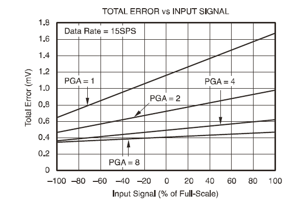
My customer is looking for the ADC conversion error/accuracy of ADS1110. They did not see it listed out directly in its datasheet. There are different kinds of errors like offset error, gain error and they are asking how they add to the total error. The ADC is configured to be 15 bits, PGA=1.


What they found from the specification of another ADC is as simple as  “Conversion Error <= 1/2 LSb”, and this is the kind of information they are looking for.

  • Rob,

    Total error looks at linearity, offset, gain, etc. as a root-sum-square.  Generally gain error will dominate the other error sources, especially as the input voltage gets closer to full-scale.  Page 5 of the datasheet shows the following graph:

    Total error is a more complete look at the result as it includes error sources from the reference, PGA, etc. besides linearity.

    Best regards,

    Bob B

  • So if we just use typical gain error, which is 1.2mv for PGA=1.  

    15 bits configuration makes each quantization step equals to 2048mv / 32768 = 0.0625mv. 

    1.2mv / 0.0625mv = 19.2, which makes ADC conversion error to be more than 4 bits.


    Is this right?

  • Rob,

    I actually calculated the gain error to be about 1mV, but the basic answer is yes the total error would be about 4bits with a full scale input.  Let's be careful about definitions.  The conversion error your originally described is most likely a linearity error only.  As each quantization step is ideally 1 LSB, the ideal transfer function would divide each step evenly within +/- 1/2 LSB.  This would be perfectly ideal.  The ADS1110 datasheet states that 'the ADS1110 loses no linearity anywhere in its input range.'  This means that the conversion from the analog input to a digital coded output is maintained within +/- 1/2 LSB.

    However this does not mean that the output is truly ideal.  If you think of the slope of the transfer characteristic being a straight line from zero to full-scale, the slope can shift up or down at the end point with gain error.  The line can shift up or down with offset error.  Even with gain and offset, the linearity is maintained.  Perhaps a better way to consider the total error is to picture a bow-tie.  A bow tie is wide at the ends (signifying gain error) and narrow at the middle where the gain error is less pronounced.

    To say that the ADS1110 has a four bit error would only be true at full scale.  When considering 'conversion error' you really should be looking at total error and not just linearity.  Hopefully I've explained why the datasheet doesn't show just a single figure of merit.

    Best regards,

    Bob B

  • The customer is using this parameter to calculate numerical errors. What is an average number that they can use?

  • Rob,

    If the average input is1/2 full-scale, then the error will be about +/- 2 LSB with offset correction  and about  4.5  +/-1/2 LSB without.  They also need to consider any noise due to a variety of factors that may supersede any error from the conversion.

    Best regards,

    Bob B