• Join
  • Sign In with my.TI Login
Texas Instruments
  • Products
  • Applications
  • Tools & Software
  • Support & Community
  • Sample & Buy
  • About TI
Sample & Purchase Cart Sample & Purchase Cart
  • Search
  • Advanced
TI E2E™ Community
  • Support Forums
  • Blogs
  • Groups
  • Videos
  • 简体中文
  • More ...
TI Home » TI E2E Community » Support Forums » Data Converters » Precision Data Converters » Precision Data Converters Forum » ADS1291 general questions
Share
Precision Data Converters
  • Forum
  • Files
  • E2E Wiki
Options
  • Subscribe via RSS
Check out
The Signal blog
  • $core_v2_blog.Current.Name

    Grounding Principles

    Posted 4 days ago
    by Bruce Trump
    In a previous blog on supply bypassing , I cautioned that poor...
  • $core_v2_blog.Current.Name

    Handy Gadgets and Resistor Divider Calculations

    Posted 11 days ago
    by Bruce Trump
    Handy gadgets make our engineering life easier—the little...
  • $core_v2_blog.Current.Name

    Chopper Op Amps—are they really noisy?

    Posted 19 days ago
    by Bruce Trump
    Chopper op amps offer very low offset voltage and dramatically...

ADS1291 general questions

ADS1291 general questions

This question is not answered
HECTOR
Posted by HECTOR
on Dec 11 2012 07:14 AM
Intellectual585 points

Hello again ;


I need to finish my  design but I need some technical supports as possible as you can and thank you in advanced.

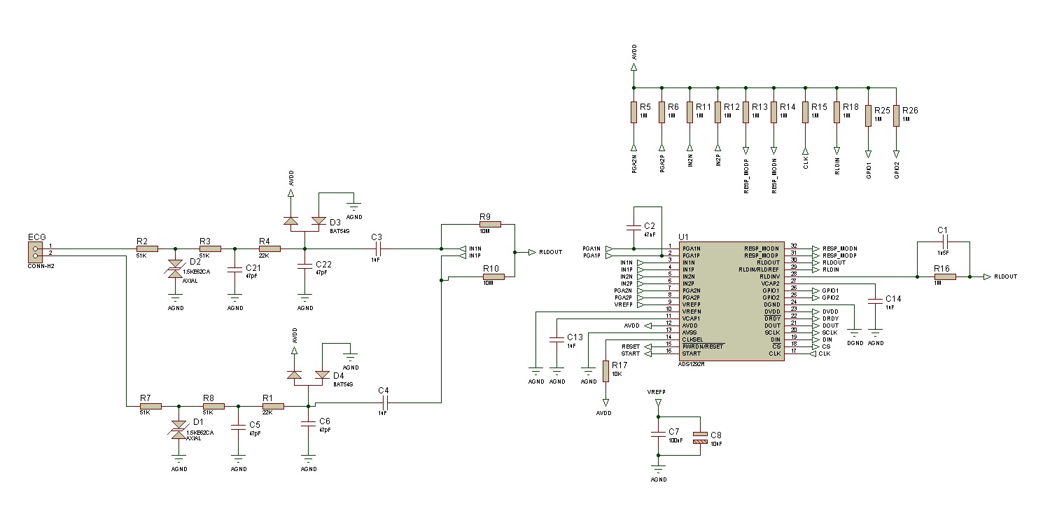
Our design depends on ADS1291 to detect  ECG signals and classify them . We would use only 2 leads there is no RLD lead . But I still need support with some issues.

1. I would use DC leadoff detection but I am using only two leads electrodes , so I cant block DC , what do you suggest a solution ?

2.  I Have to measure the impedence of the body (resistive)  the imperence between the two electrodes I could not find anything about this in the datasheet; please could you explain how to acheive that.

3. I have to detect PACEMAKER activities; hardware detection would be better but also could you suggest an example circuit to be added to ADS1291 ; know that i am using unipolar power supply (0-3.3v).If not hardware any example for software detection ?

4.Does anyone have an opensource ECG classification algorithm?

Thank you inadvanced

Hector

pacemaker
Report Abuse
  • Reply
You have posted to a forum that requires a moderator to approve posts before they are publicly available.
All Replies
  • Jairo P��rez
    Posted by Jairo P��rez
    on Dec 11 2012 07:50 AM
    Prodigy70 points

    Hello Hector,

    Please post your code so I can provide some advices.

    rgds

    Report Abuse
    • Reply
    You have posted to a forum that requires a moderator to approve posts before they are publicly available.
  • HECTOR
    Posted by HECTOR
    on Dec 11 2012 08:34 AM
    Intellectual585 points

    Thank you Jairo ;

    We still in the hardware design of the prototype ; we will start our tests and software development by the next week monday ; my problem still in understanding the issues I mentioned above.

    Report Abuse
    • Reply
    You have posted to a forum that requires a moderator to approve posts before they are publicly available.
  • HECTOR
    Posted by HECTOR
    on Dec 13 2012 01:58 AM
    Intellectual585 points

    Anyone please?

    Report Abuse
    • Reply
    You have posted to a forum that requires a moderator to approve posts before they are publicly available.
  • HECTOR
    Posted by HECTOR
    on Dec 15 2012 15:29 PM
    Intellectual585 points

    Please experts check my shematic especially for the RLD part ; since I am using one lead ECG .

    Also I have set two poles low pass filter ; of cutt off frequency about 33kHz ;


    Thank you


    Report Abuse
    • Reply
    You have posted to a forum that requires a moderator to approve posts before they are publicly available.
  • HECTOR
    Posted by HECTOR
    on Dec 15 2012 15:39 PM
    Intellectual585 points

    Also please check my PACE detector circuit.

    I still could not find solution of the common mode voltage ( unipolar supply 0-3V) ; so please could you comment on the shematic.


    Thank you

    Report Abuse
    • Reply
    You have posted to a forum that requires a moderator to approve posts before they are publicly available.
  • HECTOR
    Posted by HECTOR
    on Dec 18 2012 02:17 AM
    Intellectual585 points

    Anyone ?

    Report Abuse
    • Reply
    You have posted to a forum that requires a moderator to approve posts before they are publicly available.
  • HECTOR
    Posted by HECTOR
    on Dec 26 2012 01:35 AM
    Intellectual585 points

    The ADS1291 worked fine but I noticed all the readings is offsets by a DC volt about + 0.001volts, but I think it is ok , so you suggest a solution according to my shematic?


    But the Pace detector citrcuit did not worked ... I am still trying to built another opamp circuit to test but if you have an example or please check my circuit that seems should work ..

    Thank you in advanced


    Hector  

    Report Abuse
    • Reply
    You have posted to a forum that requires a moderator to approve posts before they are publicly available.
  • Jairo P��rez
    Posted by Jairo P��rez
    on Dec 26 2012 08:43 AM
    Prodigy70 points

    Hello Hector,

    This device has an offset error of 100uV. You can optimize the noise performance by adjusting the data rate and PGA setting. As the averaging is increased by reducing the data rate, the noise drops correspondingly. Increasing the programmable gain amplifier (PGA) value reduces the input-referred noise, which is particularly useful when measuring low-level biopotential signals. To start use a rate of 125 SPS and 2 for the PGA, then vary the gains and check the results.

    Post the code we can go deeper...

    Regards,

    Report Abuse
    • Reply
    You have posted to a forum that requires a moderator to approve posts before they are publicly available.
  • HECTOR
    Posted by HECTOR
    on Dec 26 2012 10:42 AM
    Intellectual585 points

    The code is on ARM cortex M4 there is no problem with the code it is working great; thank you Jairo for explanation;

    what about of my  pace maker detection  circuit ; I am digital man .. poor analog. but it should work but it does not ; any advice?


    Regards

    Hector

    Report Abuse
    • Reply
    You have posted to a forum that requires a moderator to approve posts before they are publicly available.
  • HECTOR
    Posted by HECTOR
    on Dec 27 2012 04:13 AM
    Intellectual585 points

    Could it be the Common Mode voltage issue here ?

    Analog guys ?

    Report Abuse
    • Reply
    You have posted to a forum that requires a moderator to approve posts before they are publicly available.
  • HECTOR
    Posted by HECTOR
    on Dec 27 2012 04:22 AM
    Intellectual585 points

    New Issue ;


    I am trying to read the ECG again and again ; as I told the reading are ok ; but there always an offset voltage added to the signal and this offset voltage not fix to subtract it each time ; some times it about 0.01V somtimes it goes to negative  , Do you suggest a solution ?

    Should a pull up resistors to AVDD to the inputs helps to make this offset fix ?


    Report Abuse
    • Reply
    You have posted to a forum that requires a moderator to approve posts before they are publicly available.
TI E2E™ Community
  • Support Forums
  • Blogs
  • Videos
  • Groups
  • Site Support & Feedback
  • Settings
TI E2E™ Community Groups
  • TI University Program
  • Make the Switch
  • Microcontroller Projects
  • Motor Drive & Control
Other Communities
  • Deyisupport
  • Designsomething.org
  • beagleboard.org
  • TI on Element 14
  • TI on TechXchangeSM
Other Technical & Support Resources
  • WEBENCH® Design Center
  • Product Information Centers
  • Technical Documents
  • TI Design Network
  • TI Technical Articles
  • TI Training

All content and materials on this site are provided "as is". TI and its respective suppliers and providers of content make no representations about the suitability of these materials for any purpose and disclaim all warranties and conditions with regard to these materials, including but not limited to all implied warranties and conditions of merchantability, fitness for a particular purpose, title and non-infringement of any third party intellectual property right. TI and its respective suppliers and providers of content make no representations about the suitability of these materials for any purpose and disclaim all warranties and conditions with respect to these materials. No license, either express or implied, by estoppel or otherwise, is granted by TI. Use of the information on this site may require a license from a third party, or a license from TI.

Content on this site may contain or be subject to specific guidelines or limitations on use. All postings and use of the content on this site are subject to the Terms of Use of the site; third parties using this content agree to abide by any limitations or guidelines and to comply with the Terms of Use of this site. TI, its suppliers and providers of content reserve the right to make corrections, deletions, modifications, enhancements, improvements and other changes to the content and materials, its products, programs and services at any time or to move or discontinue any content, products, programs, or services without notice.

Follow Us Texas Instruments on Facebook Texas Instruments on Twitter Texas Instruments on LinkedIn Texas Instruments on Google+
TI Worldwide | Contact Us | my.TI Login | Site Map | Corporate Citizenship | mobile m.ti.com (Mobile Version)

TI is a global semiconductor design and manufacturing company. Innovate with 100,000+ analog ICs and
embedded processors, along with software, tools and the industry’s largest sales/support staff.

© Copyright 1995-2013 Texas Instruments Incorporated. All rights reserved.
Trademarks | Privacy Policy | Terms of Use