This thread has been locked.

If you have a related question, please click the "Ask a related question" button in the top right corner. The newly created question will be automatically linked to this question.

4/5 scaling from TLC7528 in "voltage mode operation"

Other Parts Discussed in Thread: TLC7528, TIPD137, OPA2107, TLC072

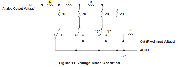
I've configured the TLC7528 as suggested in an instructable page here. This essentially feeds 5v to pins OUTA and OUTB and should give a full range of 0-5v at REFA and REFB. However I, and the person who posted the page, only have 4v output. EXACTLY 4/5 of the reference voltage. Can you explain what has been done wrong? I need a working 8-bit DAC 0-5v without the need of a 6.25v reference supply

  • More info from the instructable page

    The schematic for the DAC setup is shown above.  AGND and DGND (pins 1 and 5) connect to Arduino ground.  VDD (pin 17), OUTA (pin 2), OUTB (pin 20). RFBA (pin 3), and RFBB (pin 19) connect to Arduino 5V.  WR (pin 16) connects to digital pin 10 which is set to LOW, CS (pin 15) connects to digital pin 9 also set to LOW, and DACA/DACB (pin 6) connects to digital pin 8.  DB0-DB7 (pins 14-7) connect to digital pins 0-7.  The outputs from the DAC are pins 4 (for DACA) and 18 (for DACB).

    When a pass a saw tooth edge (0-255) to the DAC the output goes 0-4v for a ref voltage at pins2 and pin20 of 5v. Scope view at 2v per division below.


  • Lee,

    It sounds like you've got some unintentional impedance in series with your DAC output. For one, pins 2 & 3 should not be shorted when operating the device in 'voltage mode'. The feedback resistor should not be in circuit.

  • Thanks Kevin. Can you suggest an alternate circuit diagram? I am using the DAC with a single output only and the arduino is doing the buffering

  • Lee,

    Try disconnecting the feed back pin first to address your output range problem. Otherwise there is some other unexpected impedance skewing your results.

    When using the device as a BDAC (whats been dubbed 'voltage mode') there is some need to provide a buffer on the reference input because as the DAC switches move we will see a dynamic impedance which will result in changes in the current draw. The output stage also should be buffered to isolate the internal resistor network from the load. In this case you just need a voltage follower configuration on both the reference input and output.

    In the case of using the device as a MDAC ('current mode') the current draw on the reference is steady regardless of the state of the switches. In this case there is less of a need to include a buffer on the reference so long as your source is capable of sourcing the current. The output stage, however, would need an I/V conversion stage. It's pretty easy to implement a transimpedance amplifier here since Rfb is included on silicon. Diagrams for this case are illustrated throughout the datasheet.

  • Kevin,

    I read that instructable and thought the same thing. Rf was connected to Vcc. I was having trouble with circuit until I watched video about MDACs on Ti's you tube channel and realized what RFBA and RFBB were for. Could you recommend an opamp to be used for making the I to V converter? Since I am going to power this from arduino, i would need a rail to rail opamp right with sufficiently high slew rate?

  • Ayush,

    Glad the MDAC video was helpful for you.

    We wrote a TI Precision Design document concerning the selection of the output transimpedance amplifier for MDACs that you can check out here: http://www.ti.com/tool/tipd137

    The circuit discussed in that document is for a four-quadrant MDAC configuration (+/- voltage outputs), but by removing the second amplifier stage you could realize a two-quadrant MDAC configuration (single-ended voltage outputs). The first stage is where the current-to-voltage conversion is realized and what is most interesting.

    In short, rail to rail performance and slew rate considerations are really more auxiliary concerns for your design based on your own requirements. The most important specifications of the amplifier to maintain the specifications of the MDAC are input bias current and input offset voltage.

  • Is there any advantage of using in current mode? I am not using a variable reference voltage. I just need a Vref output if that's possible in voltage mode.

  • Ayush,

    Depending on which device you are looking to do this with, there could be advantages to using the device in current output mode. Linearity has the potential to degrade in the voltage output configuration for high resolution devices because the of the DAC switches. These switches are comprised of two FETs where one is connected to GND and the other to IOUT. In current output mode with a transimpedance amplifier on the output, both of these nets are connected to GND or virtual GND so the FETs are biased with the same Vgs. In voltage output mode the IOUT net is biased to some potential which biases the FETs differently that results in their on resistances not matching, causing a linearity error. This is most significant for high resolution devices.

  • Thank you Kevin for your time, I am just using it to create waveforms using arduino, it requires a buffer in voltage mode right? So why not use it in current mode if you are going to use an opamp anyway. I have a couple of OPA2107 and TLC072 lying around. Do you think TLC072 would be enough? I hate to use dual power supplies unless it's for audio applications

  • Ayush,

    Yes, a buffer amplifier is required in voltage output mode to isolate the internal resistor ladder from the impedance of the load. The advantage that is in this case the output is the same polarity as the reference, that is with 2.5V VREF the output swings from 0 to VREF. In current output mode the trans-impedance stage inverts the output polarity with respect to the reference, that is with 2.5V VREF the output swings from 0 to -VREF. The big trade-off is linearity / accuracy for convenience.

    It would help to know which DAC you want to use before confirming either of those amplifiers.

  • I am using TLC7528.It's a 8 bit DAC. Looks like i will be using the voltage output mode

  • Ayush,

    As it concerns choosing the amplifier in voltage output mode, the input bias current and offset voltage specifications aren't as important to avoid parametric degradation of the voltage output of the DAC. The performance at the Vref output is going to be pretty static regardless of the amplifier. You should be aware, though, that the amplifier will add an offset to the rest of the signal chain due to Vos. So based on your accuracy goals, you may look at amplifiers with lower Vos.

    The TLC7578 datasheet is a little old and doesn't specify slew rate, we only get settling time. You'll want to take a look at the slew rate of the DAC in this voltage output configuration and make sure that the amplifier matches it's slew rate performance or that it doesn't have back-to-back protection diodes on its input. You can sometimes infer this from the datasheet, other times you may need to ask on the linear E2E forum or just do some simple experiments in the lab. It will be very apparent

  • Regarding the voltage-mode operation of the TLC7528:

    I am trying to understand the demands put on the reference in this operation mode so what impedance intervall can be expected on the OUT-pins? I understand that it depends on the code but is a 5mA, a 10mA or a 20mA reference sufficient?

    In order to reduce components and cost I would rather avoid a separate buffer.

    Any suggestions on suitable, cheap references (or reference + buffer) are more than welcome.  :)

    One more thing.

    The leftmost resistor in Figure 11 in the TLC7528 datasheet, is it really there or is it a "typo".

  • Hello Mikael and welcome to the e2e forums! The equivalent impedance of R is specified in the datasheet as the following:

    Figure 11. displays an example of a current multiplying DAC that operates in voltage mode. The correct figure to use for your calculations is the Figure 1 schematic, which is a simplified functional circuit for DACA. I've provided the picture below for reference.

    Since the equivalent resistance of the R2R network is 'R', it should be easy to understand that the current consumption required from Vref is I=Vref/20kohm.

    Best Regards,

    Matt

  • Hi Matt, and thank you for your reply.

    Actually I am interested in using the circuit in voltage mode and then the reference is connected to the OUT-pin. Of course it is still possible to calculate the equivalent series resistance but now it varies with code, right? The datasheet only specifies the maximum input impedance but I am rather interested in the minimum or typical impedance (=minimum and typical value of R).

    Best regards,

     MIkael

  • Mikael,

    Generally speaking all silicon processes aren't so good at delivering absolute value resistors, instead they're really good for maintaining good matching between resistors to achieve precise performance. A general rule of thumb for absolute value resistor tolerance for most processes can vary +/-20%. Assuming that the old process that this part was produced on is similar, which is a pretty safe assumption, the typical value should be ~16.7kOhm and the minimum would be ~13.3kOhm (i.e. +/-3333.3ohms about 16.666667kOhms).

    Again - it's an old part so it's difficult for me to access the design database to confirm or deny, but, I think the series resistor you asked about in the earlier post is a typo. If this resistor were present the output current at IOUT would be VREF/2R and the R value feedback resistor in the transimpedance stage would only produce a VREF/2 voltage output.

    Hope this helps

  • Thanks for this Kevin.

    What I am after is an R2R-ladder with integrated switches between VREF and AGND but no amplifier. The reason to this is that my digital input to the R2R is controlled by two different controllers. One that outputs a waveshape and another one that PWMs the digital signals in order to scale the amplitude of the signal. This means that the analog output from the R2R also is PWM:ed and that a filter is needed. My plan was to use the buffer amp as a two pole Sallen Key link instead and the R2R series equivalent resistance will therefore be a resistance in the filter.

    Are there any newer products that would fit my needs?

    Thanks!

  • Hi Mikael,


    You are correct, when looking in from the OUT-pin, the impedance changes by code.

    There is no easy way to determine the impedance at each code. If you want some more detailed information to calculate it take a look at TIPD137. The document does not focus on using an MDAC as a voltage output, rather it focuses on choosing the output transimpedance stage amplifier which also has to deal with the changing impedance.

    As a good approximation you can expect:

    • 3*R    at Code 1
    • 0.3*R at Full Code

    It's a fairly linear relation.

  • Thank you Eugenio for the very informative and helpful app note!

    /Mikael

  • This is an old thread, but I'm going to jump in here anyway because I just ran into exactly the same problem that the OP asks about. As near as I can figure out by trial and error, no thanks to the data sheet, the TLC7528 works in "voltage-mode" ONLY if the Fixed Input Voltage is at least some fixed minimum amount below Vdd. If Vdd is 5V then a Fixed Input Voltage of 5V results in incorrect Analog Output Voltages as the OP mentions. However, if the Fixed Input Voltage is, say, 2.5V (as it is in the test conditions for voltage mode linearity) then it works just fine. It would have been nice if the data sheet, or the TI engineers on this forum, had mentioned this rather than leaving it as an exercise for the reader.