This thread has been locked.

If you have a related question, please click the "Ask a related question" button in the top right corner. The newly created question will be automatically linked to this question.

ADS1292 DOUT pin remains always low during SPI communication

Other Parts Discussed in Thread: ADS1292R, ADS1292, ADS1298

Hi,

I have been working with ADS1292R for several weeks but still cannot get it to work.

The problem is that, no matter what I try, registers can be written (as far as I can tell) but no read. Hardware connections have been double checked, two identical PCBs were assembled with same results and different SPI configurations have been tested.

Did anyone experience the same problem? Do you have any troubleshooting suggestions?

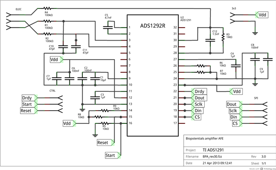
Can you find the cause for this on the below code, SPI configuration or schematics that I am using?


- ADS1292R is connected to a PIC32MX250F128B.

- SPI configuration: Idle state for clock is a low level, serial output data changes on transition from Idle clock state to active clock state and input data sampled at middle of data output time (CKP=CKE=SMP=0); SCLK freq.: 1MHz.

- Register write code:

SPI1CONbits.ON = 1; // SPI module on

PORTBbits.RB15 = 0; // CS low

SPI1BUF = ReceivedDataBuffer[1]; // WREG OPCODE1, say 0x42

while(SPI1STATbits.SPIBUSY);

SPI1BUF = 0x00; // WREG OPCODE2

while(SPI1STATbits.SPIBUSY);

SPI1BUF = ReceivedDataBuffer[2]; // REG DATA, say 0x88

while(SPI1STATbits.SPIBUSY);

ShortDelay(140); // approx. 4T_clk delay

PORTBbits.RB15 = 1; // CS high

SPI1CONbits.ON = 0; // SPI module off

- Register read code:

SPI1CONbits.ON = 1; // SPI module on

PORTBbits.RB15 = 0; // CS low

SPI1BUF = ReceivedDataBuffer[1]; // RREG OPCODE1, say 0x20

while(SPI1STATbits.SPIBUSY);

SPI1BUF = 0x00; // RREG OPCODE2

while(SPI1STATbits.SPIBUSY);

SPI1BUF = 0x00; // MOSI low during data reading

while(SPI1STATbits.SPIBUSY);

ToSendDataBuffer[1] = SPI1BUF; // REG DATA

ShortDelay(140); //approx. 4T_clk delay

PORTBbits.RB15 = 1; // CS high

SPI1CONbits.ON = 0; // SPI module off

- ADS1292R schematics is as follows:

- For example, by sending first a RESET command (0x06), I can write 0x01 or 0x02 to GPIO and read the corresponding levels on GPIO1/2 pins. Or I can also write 0x88 to CONFIG2 and then read 512.9KHz on CLK pin, this is how it looks like:


- But, whenever I try to read a register (anyone) always read 0x00

- Also checked DOUT pin disconnected from the PIC32 MISO pin (with the logic analyzer), to rule out problems caused by the microcontroller, but it's the same: DOUT remains low for the entire transaction.


At this point I am just keeping my fingers crossed to make this work :-)

Thanks in advance for your time and suggestions!

Esteban


  • Any solution?? I seem to be having the same problem. THANKS
  • Unfortunately, none. I tried everything I knew and reached a point where I decided to exclude ADS1292 from my design. If you find something, please post it. This would be a very convenient circuit for me, If I could make it work.

    Thanks,

    Esteban

  • Try a pull-up on the START line. It looks like yours is tied to ground.

  • Hi TI guys


    I have same problem, the DOUT always low. And I checked the DOUT, no short circuit with GND. Would you please help check this problem, it has been blocked me for few days.

    By now I tried following tests:

    Test 1. Issue reset squence --> issue SDATAC to stop read data continuously mode --> Read ID of ADS1292 through SPI, DOUT is keeping low voltage.

    Test 2. Issue reset squence, then pull high START, I can see the DRDY* is working on oscilloscope. Then start SPI on MCU to try to read ADS1292, at this moment, SCLK, CS*, DRDY* is working correct. But DOUT still keeping low. (I have experience of using ADS1298, it works fine, so I know the correct behavior of DRDY*, now the DRDY* of ADS1292 has same behavior with ADS1298, so I think the ADS1292 is working now, at least the input signals CLK, SCLK, CS* should has no problem)

    Appreciate for your help in advance.

  • Hi all,

    It seems that this post is one year old, but there is no answer. I have the same problem. Did you guys manage to find the problem?

    My condition is that:
    - DOUT is definitely not connected to its neighbor pins (and also other tracks).
    - DOUT is connected to its track and the chip is driving the line (it is not floating). I checked it by adding a pull-up resistor to my measuring prob.
    - The chip receives the commands from MOSI correctly, since it is able to start and stop the conversion (after receiving the commands) and toggle the DRDY pin. Therefore, the chip is powered up and the clocking source is correctly activated. (internal clock source in my case).

    Thanks in advance.
  • Hey V324O,

    It's possible that your protocol is correct for the other commands but is incorrect for the RREG command. Can you post a picture of your RREG SPI transaction from a scope or logic analyzer?

    Regards,
    Brian Pisani
  • Hi Brian,

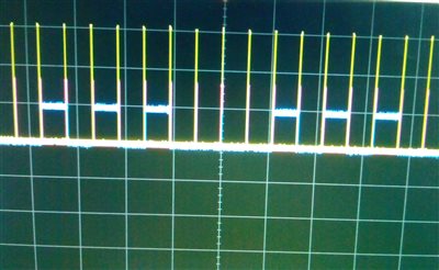
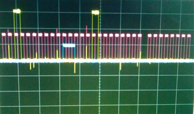
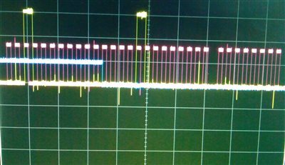
    Thanks for answering. Well, the strange thing is that when I send the START and STOP commands once the DOUT pin gives some responses. I tested the same code without sending START and STOP commands and the DOUT remained low (in this case the DRDY was not toggling). However, even when the DOUT pin toggles, the MCU doesn't receive any reasonable response. This can be seen in the images below.

    Blue: DOUT

    Yellow: DIN

    Red: SCLK

    The package is for reading the ID register (like the example in page 38 in datasheet). The number of registers to be read is chosen to be 2 (so I am sending one as the second byte). Since I am using ADS1292R I should receive 0x73 I think. The same package is sent in every transmission but DOUT is sending out different packages each time which none of them is 0x73. This can be seen from the first image which is a zoom out version of the transmission.

    Thanks,

    Regards

  • Hey V324O,

    Is the Chip Select pin being held low for the entirety of the transaction? I know some microcontollers will pulse it high between bytes. That would explain why you can do the single byte commands like STOP and START.

    Regards,
    Brian Pisani
  • Brian,

    I'm not using the internal hardware-based SPI block of the MCU. I wrote the SPI library myself. So I am sure that CS is being hold low in the whole prcoss, since the MCU starts up.

    Regards

  • Hey V324O,

    Are you able to successfully write registers?

    Brian
  • Hi Brian,

    I will test that with GPIO register and tell you the result.
  • Brian,

    I can successfully write registers. I wrote the GPIO registers to drive an LED. 

    Thanks

  • Hey V324O,

    Are you issuing the SDATAC command before you attempt the read?

    Brian
  • Hey Brian,

    That was the problem. I sent the SDATAC command before doing anything else and the problem was solved. Thank you so much.

    Regards

  • Hey V324O,

    Glad to hear it. Let us know if you need any more help.

    Brian Pisani
  • I have simmilar problem. But i know i cant write registers.
    There is no effect for example ;SDATAC, StopConvertion from register, Clk out enable from Config2 register. So i thing cant write to register.
    If i do nothing after reset i got data from DOUT but if i stop convertion with start pin. I read nothing.

    Do you have any suggestion. Did you solved???
  • Hello Ferhat,

    Can you please list your sequence from startup until you can no longer read from the device? Then, can you please look at the transaction on the oscilloscope or logic analyzer and post the screen capture here for me to analyze?

    Brian