This thread has been locked.

If you have a related question, please click the "Ask a related question" button in the top right corner. The newly created question will be automatically linked to this question.

ADS1256 continuous output from data-out

Other Parts Discussed in Thread: ADS1256

I bought a pre-built ADS1256 board from Aliexpress.com.  I hooked it up to an IOIO OTG via SPI but could only get garbage data from it.  I then hooked up a logic analyser and confirmed that my SPI signals going in to the ADC are correct.

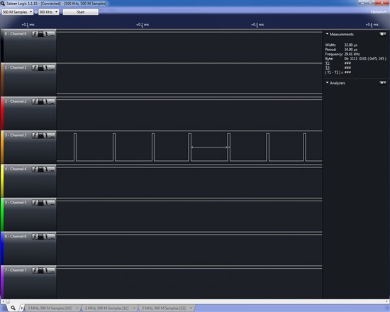
I then noticed that the ADC is outputting a single 2 or 4 us pulse every 32us.  The data-ready pin seems to have worked correctly in response to SPI commands, but the data-out never changes.  I have done SDATAC as well.  Is this chip faulty perhaps?

  • Hi Duncan,

    Welcome to the TI E2E Forums!


    The /DRDY pulse indicates that the ADC is performing conversions. The 32us period corresponds to a data rate of about 30 kSPS (the default data rate). That is a good sign that the chip is working!

    Are you sending SCLK?
    To get the data output you will need to clock out all of the data
    (...faster than the ADC's data rate - I would recommend slowing down the data rate by changing the value set in the DRATE register).  I do not see a clock signal in your screenshot above.

    Here is an example of what the SPI communication should look like:

    8507.single channel.logicdata

    You will need to generate the SCLK and DIN signals, (SCLK at a minimum) then you will see DOUT changing.


    Best Regards,
    Chris

  • Hi Chris, thanks for the reply.  I really look forward to this board working.

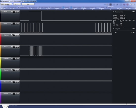
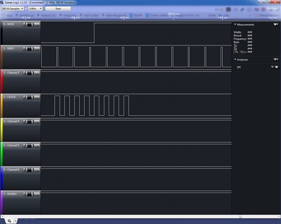
    I agree that the  /DRDY pulse indicates that the ADC is performing conversions.  But I am still just seeing pulses from data-out.  I included here two more images, showing SCLK, DIN and DOUT.  /CS is tied low and /RESET is tied high.  I did not connect /DRDY to the analyser this time.

    SCLK is running at 50K.  My understanding is that I can choose any SCLK frequency up to 2Mhz to communicate with the board, but I never seem to get any data out.

    Pictures show what happens when I send RESET and SDATAC.

  • It is my understanding that the chip defaults to RDATAC mode after power up and that RESET or SDATAC will cancel continuous conversions.  The supplier states that he tested the board before mailing it to me, so I'm a bit lost as to why I'm not getting expected functionality from it. 

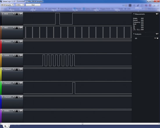
    I also tried reading from various registers but the continuous output pulses persist.  Below is the read from MUX results.  This was done after a SDATAC and then SYNC and then WAKEUP were issued.  /DRDY is on channel 5.

    The chip appears to work except for the output.

  • Hi Duncan,

    Your channel labeled "MISO" appears to behave like /DRDY. Its period would correspond with the default data rate of 30,000 SPS. Perhaps double check to make sure the PCB silkscreen labels are correct and make sure you're not probing a different signal.

    Also, check that you are using the correct SPI mode (CPOL = 0, CPHA = 1).

    If you are still concerned about the device not working, you should be able to order some free samples to swap with the installed device here: http://www.ti.com/product/ADS1256/samplebuy.

    Regards,
    Chris

  • Hi Duncan,

    I just want to follow up and see if you were able to resolve this issue. Have you made any progress?

    Regards,
    Chris

  • Hi Chris

    Yeah, its working fine.  My confusion came about because the Dataready signal continues to pulse at what ever conversion rate you specify.  This is expected in continuous conversion mode but unexpected in all other modes.  I was expecting the SDATAC command to stop those pulses, but it does not.  Some clarification of this in the datasheet is needed.

    Other than that it is an impressive product.

  • Thanks for the feedback!

    I'll make a note to add some clarification to the ADS1256 datasheet the next time a revision is published.

    Best Regards,
    Chris