This thread has been locked.

If you have a related question, please click the "Ask a related question" button in the top right corner. The newly created question will be automatically linked to this question.

ADS1281 with a PIC32 register mode

Other Parts Discussed in Thread: ADS1281

I'm using an ADS1281 with a PIC32MX695F512L-80I/PT Microprocessor from microchip. I can get pin mode to work fine. I need to use register mode though so that I can control timed throughput. I can't seem to get register mode going. I've been through all of the forum subject matter. I haven't succeeded yet in getting the DRDY signal to happen. This causes the external interrupt to fire.  Actually, I tried reading Register 0, 1 and 3.  I couldn't even read the registers reliably. Can anyone help me get my head on straight.  I'm starting with just trying to read register 3.

The Pin Mode PIN (Pin 21) is set to 0.

fclk is 4.096 Mhz.  So only need 8uS between commands.

Here is my code:

int main(void)
{
int rdData1;
int input;
INPacketIndex = 0;
tickcount = 0;
timercount = 0;
int k;

InitializeSystem();
SpiInitDevice(SPI_CHANNEL1, 1, 0, 1); //8 bit
SpiChnClrIntFlags(SPI_CHANNEL1); //Clear Spi Interrupt
for(k=0; k< 8; k++) //Cause a reset
{
SpiChnPutC(1,0x00);
SpiChnGetC(1);
}
SpiChnPutC(1, 0x11); // Stop read data continuous
rdData1 = SpiChnGetC(1);
Delay10us(0x2a);

//check the chip ID
SpiChnPutC(1, 0x21);
rdData1 = SpiChnGetC(1);
SpiChnPutC(1, 0x00);
rdData1 = SpiChnGetC(1);
SpiChnPutC(1, 0x00);
rdData1 = SpiChnGetC(1);


OpenTimer2(T2_ON|T2_IDLE_CON|T2_PS_1_256|T2_SOURCE_INT, 62500);
ConfigIntTimer2(T2_INT_ON | T2_INT_PRIOR_7);

}

void __ISR(_TIMER_2_VECTOR, ipl7) Timer2_Interrupt(void)
{
int rdData1;
//read register 3 should always be 0x52
SpiChnPutC(1, 0x23);
rdData1 = SpiChnGetC(1);

SpiChnPutC(1, 0x00);
rdData1 = SpiChnGetC(1);

SpiChnPutC(1, 0x00);
rdData1 = SpiChnGetC(1);

mT2ClearIntFlag();
}

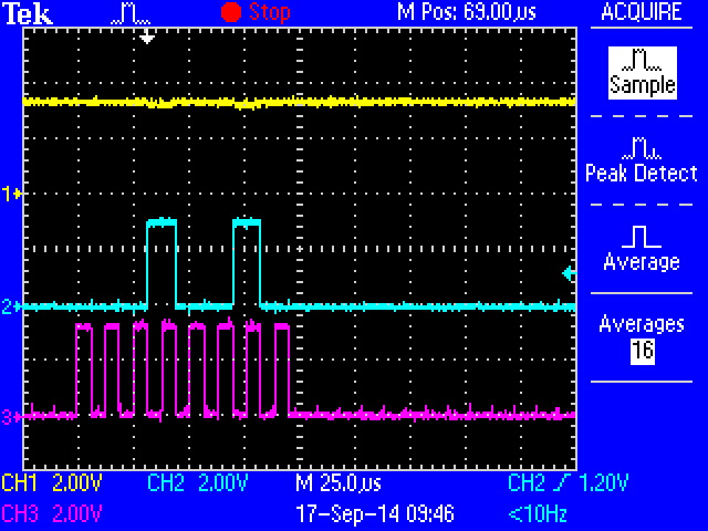
 When I run this code I get 0x00000000 in rdData1.  Looking Dout (pin 4) with a oscilloscope.

I would appreciate the help.

Thanks in advance.

  • Hi Jim,

    Welcome to the TI E2E forums!

    The ADS1281 should begin converting after power-up. Hence, you should see /DRDY toggling, without sending any SPI commands; though it takes a longer time for this device - the settling time for the FIR filter (default configuration) is 62 conversion cycles.

    The ADS1281's SPI commands are also a little different than some of our other delta-sigma ADC's...

    When you send SDATAC in you code, you will suppress the /DRDY output. In this mode (read data by command), you must send an RDATA command (just to enable the /DRDY signal). After /DRDY goes low - you can then clock out the data. (RDATA must be sent prior to each conversion to read out the data.)

    So the "read data by command"  behavior is a little odd. It is intended to be used when you occasionally capture data. Also, you must put the device in this mode when configuring the register settings.

    If you want to capture data with each conversion, it would be more practical to use the "Read Data Continuous" mode, by sending RDATAC (after you have configured the registers).

    Best Regards,
    Chris

  • Thanks for your reply.  However, when I perform the RDATA command, for some reason, it is not producing the /DRDY output. And yes I have sent the SDATAC command to stop continuous data.  I actually don't want every conversion.  I'm looking to gather data at 5 Hz, 10 Hz, 50 Hz, 100 Hz and 200 Hz rates.  I will select these different rates by changing the rate of my timer interrupt.

    Also, It seems that I can't read the contents of the Config registers Properly.

  • Hi Jim,

    Are you able to capture an oscilloscope or logic analyzer screenshot of the SPI communication?
    That is always a good sanity check to make sure the code is doing what you think it should be doing.

    Best Regards,
    Chris

  •  nnnn

    Hi Chris,

    The image of the scope is above.  Yellow is the /DRDY line, Blue is DIN and maroon is SCLK.

    The /DRDY is not being asserted after the Read Data Command.

    Am I missing something?

    Below is my code again.  Am I forgetting a configuration step?

    New information:  It seems that the SDATAC is really not getting processed properly by the ADS1281.  I can do any command to the device and the continuous operation of the device stops.  So, it seems that the register mode on this device is not working at all.

    I comment all of the commands and the device returns to Read Data continuous mode, my /DRDY starts up again and I can then retrieve data from the device.

    Any further comments would be greatly appreciated!!

    Does anybody have any further input?

    There seems to be some interest in this topic judging by the number of views.

    int main(void)
    {
    int rdData1;
    int input;
    INPacketIndex = 0;
    tickcount = 0;
    timercount = 0;
    int k;

    InitializeSystem();
    SpiInitDevice(SPI_CHANNEL1, 1, 0, 1); //8 bit
    SpiChnClrIntFlags(SPI_CHANNEL1); //Clear Spi Interrupt
    for(k=0; k< 8; k++) //Cause a reset
    {
    SpiChnPutC(1,0x00);
    SpiChnGetC(1);
    }
    SpiChnPutC(1, 0x11); // Stop read data continuous
    rdData1 = SpiChnGetC(1); //Clear Spi read buffer.
    Delay10us(0x2a);
    SpiChnPutC(1, 0x41); // Write register 1
    rdData1 = SpiChnGetC(1); //Clear Spi read buffer.
    Delay10us(0x2a);
    SpiChnPutC(1, 0x00); //Just one register
    rdData1 = SpiChnGetC(1); //Clear Spi read buffer.
    Delay10us(0x2a);
    SpiChnPutC(1, 0x42); // High resolution, 250 SPS, Sinc + LPF
    rdData = SpiChnGetC(1); //Clear Spi read buffer.
    Delay10us(0x2a);

    OpenTimer2(T2_ON|T2_IDLE_CON|T2_PS_1_256|T2_SOURCE_INT, 62500);
    ConfigIntTimer2(T2_INT_ON | T2_INT_PRIOR_7);


    ConfigINT1(EXT_INT_PRI_1 | FALLING_EDGE_INT | EXT_INT_ENABLE);
    mINT1SetIntPriority(3);
    INTSingleVectorRegisterSet(0);
    INTConfigureSystem(INT_SYSTEM_CONFIG_SINGLE_VECTOR);
    mINT1IntEnable(1);
    PORTSetPinsDigitalIn( IOPORT_E, BIT_8 );

    #if defined(USB_INTERRUPT)
    USBDeviceAttach();
    #endif

    while(1)
    {
    #if defined(USB_POLLING)
    // Check bus status and service USB interrupts.
    USBDeviceTasks(); // Interrupt or polling method. If using polling, must call
    // this function periodically. This function will take care
    // of processing and responding to SETUP transactions
    // (such as during the enumeration process when you first
    // plug in). USB hosts require that USB devices should accept
    // and process SETUP packets in a timely fashion. Therefore,
    // when using polling, this function should be called
    // frequently (such as once about every 100 microseconds) at any
    // time that a SETUP packet might reasonably be expected to
    // be sent by the host to your device. In most cases, the
    // USBDeviceTasks() function does not take very long to
    // execute (~50 instruction cycles) before it returns.
    #endif

    // Application-specific tasks.
    // Application related code may be added here, or in the ProcessIO() function.
    ProcessIO();

    input = PORTEbits.RE8;

    }//end while
    }//end main

    void __ISR(_TIMER_2_VECTOR, ipl7) Timer2_Interrupt(void)
    {
    int rdData1;
    SpiChnPutC(1, 0x12); //Read Data By Command
    rdData1 = SpiChnGetC(1);
    mT2ClearIntFlag();
    }

    Best Regards,

    Jim Gale

    Wasson-ECE Instrumentation, Inc.

  • Hi Chris,

    Ok,  I was trying to get register mode working, because I thought it would be the cleaner approach.  It seems that I can't send any commands to the ADS1281.  This includes the SDATAC command.  It seems any command stops the continuous read.  However, I can't seem to write or read any registers beyond that.  I'm sure I'm missing something.

    I do have a work around.  It's not as elegant and being able to control the AtoD through software.   I can do pin control to set sample rates and do continous data collection.  I can set up a timer interrupt at the data rate that I want and only use the current reading.

    My thought that if the register mode is described in the data sheet, it should be usable.

    Oh, I'm using the ADS1281 because it actually has a highter resolution than 24 bit.

    Best Regards,

    Jim Gale

    Wasson-ECE Instrumentation, Inc.

  • Hi Jim,

    I think I see the issue now...

    From the oscilloscope screenshot you posted, the SCLK looks to be about 80 kHz. This is too slow! There is a minimum SCLK frequency requirement of "fclk/16"  ...therefore 4.096 MHz / 16 = 256 kHz.

    I think this is preventing the ADS1281 from correctly recognizing the SPI commands. Are you able to increase the frequency of SCLK?


    A quick side note:

    • In your code, are you implementing an SPI reset here?:

    for(k=0; k< 8; k++) //Cause a reset
    {
    SpiChnPutC(1,0x00);
    SpiChnGetC(1);
    }

    To reset the SPI you need to hold SCLK low for 64 conversion cycles (1000 SPS -> 64 ms). Instead of clocking out "0x00", I would recommend just using a delay, ...if resetting the SPI is the intent.

    Best Regards,
    Chris

  • Hi Chris,

    I had already tried this yesterday. However, here are the results:

    So here is the trace at 322.580 khz sclk. Still no /DRDY.

    I also now just insert a 256 mSec delay between my SpiInitDevice and any of my commands.

    Best Regards,

    Jim Gale

    Wasson-ECE Instrumentation, Inc.

  • Hi Jim,

    Sorry to have not gotten back to you last week. Have you been able to resolve this issue?

    If you are not seeing /DRDY at all after power up  I would presume one of the following:

    • Either "fclk" is not starting up, or one of the digital pins ("/PWDN" or "/RESET") is being held low.
    • It is possible for the device to go into a latch-up state on power up if voltages are applied to any of the pins that exceed the supply voltage.
    • The device has otherwise been damaged.

    From power up to the first /DRDY will take some time... About 63ms (according to  Figure 42 and Table 13 on page 22 of the data sheet).

    Best Regards,
    Chris

  • Hi Chris,

    I've actually just been using the device in Read Continuously mode.  I'm actually getting /DRDY pulses and am able to access the output data just fine.

    The problem i"m having is that I can't seem to write commands to the device.  When I write the SDATAC command or any command to the device it stops the Read data Continuously and after that it won't accept any further commands. This includes the RDATAC command.  The command in the piicture is the Read Data by Command.  As you can see after sending that command, I don't get the /DRDY pulse.  I also cannot restart Read Data Continuously again without restarting the system from scratch.

    I do need to get the register mode working because I need to cause zero and gain calibrations to occur.

    I am running the device in unipolar mode.  I found that there is an offset that needs to be corrected through calibration.  

    If you see no problems in my code, then I'm wondering if there is a problem with the DIN pin.  

    Thanks for the reply.

    Best Regards,

    Jim Gale

    Wasson-ECE Instrumentation, Inc.

  • Hi Jim,

    This is very bizarre! I've checked with the digital designer and there is no mode or time period that would prevent you from sending "RDATAC" and re-entering "read data continuously" mode.

    Try this test...after writing to the device registers, read them back to see if the settings you write are taking. If so, we know the PIC32 and the ADS1281 are correctly interpreting each others SPI words. If not, then perhaps there is a timing requirement we're both missing.

    Also, if you would send me a shipping address and I will send you some free samples so you can also try replacing your ADS1281 in the case that it is damaged. You can email me your information at pa_deltasigma_apps@ti.com.

    Best Regards,
    Chris

  • Hi Chris,

    The problem is solved.  I can now read and write registers.  The problem was that the pinmode was not physically going to zero.  The code said it was supposed to be zero, but it wasn't.  I'm sorry for the trouble.  Once I used a volt meter to check it, the problem then was resolved.

    You can close this case.

    Best Regards,

    Jim Gale

    Wasson-ECE Instrumentation, Inc.

  • Hi Jim,

    Hurray! I'm glad you were able to solve problem :)

    Let me know if I can help with any other issues!

    Best Regards,
    Chris

  • Hi Chris,
    We have experienced the same problem.We also can't get register mode going. Could you send some free samples to us.Thank you .
    Email:jw5128@126.comBest Regards
  • User436186,


    First what have you tried to get register mode going? Are you getting bad reads? Can you not change registers? You'll have to describe the problems you are having and what it not working. I would also help to have scope shots if the data is coming back wrong.

    For free samples, you can request them for yourself. Go to the appropriate product folder (in this case the ADS1281) and go to the Sample and buy folder.

    www.ti.com/.../samplebuy

    From there, you can request a sample. You'll need to fill out some information about yourself, the application, and the company you work for, but should be able to get them.


    Joseph Wu