This thread has been locked.

If you have a related question, please click the "Ask a related question" button in the top right corner. The newly created question will be automatically linked to this question.

ADCPro for ADS1278EVM buggy?

Other Parts Discussed in Thread: ADCPRO, ADS1278

Hello,

   I've had a rather dismal experience using the ADCPro software with the ADS1278EVM.  It keeps crashing, but more specifically, the clock settings seem to be all screwed up.

1. When you start, the default settings are:

Data Rate (DR): 128.001k

Clock Frequency (CF): 32.768M

Modulator Frequency (MF): 8.192M

2. If I select High Res and then select back to High Speed mode, the settings are now:

DR:105.469k   CF:27M   MF:6.75M

3. Now if I select Low Power mode:

DR:52.734k   CF:27M   MF:3.375M

4. Now select CLKDIV=0:

DR:52.734k   CF:13.5M   MF:3.375M

5. Select High Speed mode: (CLKDIV automatically goes to 1)

DR: 52.73   CF:13.5M   MF:3.375M

6. Select Low-Power mode again:

DR:26.367   CF:13.5M   MF:1.6875M 

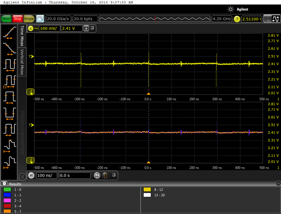
So now the data rate is different, even though it's the same configuration as (3).  Screenshot from scope for this final configuration suggests that the modulator frequency is actually 3.375MHz.

I spent a lot of time trying to figure out why the numbers weren't matching up and went through the trouble of setting up this fancy scope, so fix it, please?

-Mike

  • Hi Mike,

    Thanks for your post. I do understand what you're seeing, but I assure you that it is not a bug. Instead, the GUI is trying to protect you from using a clock that is faster than the accepted maximum for the selected mode. It will also change CLKDIV back to '1' if the new mode you selected does not support it.

    At start-up, the EVM is configured to use a 32.768MHz clock in High-Speed Mode. Upon switching to High-Resolution mode, the GUI will lower the clock to the maximum allowable clock frequency for that mode (27MHz). When you switch back to High-Speed Mode, 27MHz is still an acceptable master clock, so the GUI will leave it as is.

    So in Step 6, you are using the ADS1278 in Low-Power Mode with a master clock of 13.5MHz, which produces an output data rate of 26.367kSPS. You can type "27.000" in the "Clock Frequency" field and see the Modulator and Data Rate fields update. If you try to enter a clock that exceeds the maximum for the current mode, the GUI will reset the clock to whatever the maximum is.

    Keep this table in mind when choosing different modes for the ADS1278:

    Mode Selection

    Max fCLK

    (MHz)

    CLKDIV

    fCLK/fDATA

    fMOD

    OSR

    High-Speed

    37

    1

    256

    fCLK/4

    64

    High-Resolution

    27

    1

    512

    fCLK/4

    128

    Low-Power


    27

    13.5

    1

    0

    512

    256

    fCLK/8

    fCLK/4

    64

    64

    Low-Speed

    27

    5.4

    1

    0

    2,560

    512

    fCLK/40

    fCLK/8

    64

    64


    Best Regards,

  • So if the modulator frequency is supposed to be 1.6875M, why does the waveform have a period of 300ns?

  • Hi Mike,

    True, a modulator clock of 1.6875MHz would have a period of 593ns. But I do not recognize that waveform as a modulator clock. If I had to guess, that looks like you are probing the reference pin to see the current drawn during the ADC sampling period. If not, please explain what it is.

    You can verify the ADS1278 modulator clock directly by placing the device in Modulator Mode (please refer to page 35 of the datasheet). FORMAT[2:0] must be set to 110 and DIN pulled high. Then, you can measure the modulator clock output on the SCLK pin for different MODE[1:0] and CLKDIV settings.

    Perhaps even simpler, probe the /DRDY / FSYNC pin and look at the resulting data rate. Then multiply the data rate by corresponding OSR in the table I provided above to calculate the modulator rate.

    Best Regards,

  • Ryan,

       The plot is measuring the inputs of the ADC.  My SPICE simulations showed that the input capacitor might actually not get fully charged in time, so I wanted to check.  I'm using a high bandwidth differential active probe, directly probing the differential input pins of the ADC.  The big downward spikes I assume are caused by the ADC sampling the inputs.

  • Hi Michael,

    You would be correct, the larger spikes correspond to when the inputs are sampled. I am still reluctant to believe that the mod clock is off by 2x - the reference might sampled at twice the modulator rate, but not the inputs. I am talking to the designers to learn exactly how the ADS1278 sampling network is structured. Perhaps the way it is implemented can explain this.

    Meanwhile, if I can get my hands on a differential active probe, I will try to repeat your experiments next week.

    Did you compare the results from your scope plot to the modulator clock output in Modulator Mode? You should be able to record both simultaneously and see how the spikes line up with the rising/falling mod clock edges.

    Best Regards,

  • Sorry, I didn't measure the modulator clock, since I was more concerned about the settling time of the opamp.  Looking at the traces, it seems like there is a slight upwards ramp after each sampling, and it seems to still be going upwards when the ADC stops sampling.  Is this indicative of the capacitor charging too slowly?

  • Hi Michael,

    I'm not entirely sure. Could you show me the scope capture?

    Also, regarding your original question, I would like to get some more information from you offline. May I contact you at the email address you provided in your profile?

    Regards,

  • The scope capture is on my first post, you can see a slight upwards ramp on the voltages.  You can contact me by email.