This thread has been locked.

If you have a related question, please click the "Ask a related question" button in the top right corner. The newly created question will be automatically linked to this question.

TLV5630 DAC SPI Daisy Chain

Other Parts Discussed in Thread: TLV5630

Hi, 

I want to daisy-chain two TLV5630 DAC's.
In the manual page 10 I read "For daisy-chaining, DOUT provides the data sampled on DIN with a delay of 16 clock cycles.". However, how do you acces DAC outputs 9 - 16? If the DOUT just feeds trough the data bits channel 1 of DAC 1 & 2 have the same outputs?

Thanks in advance,
Kevin

  • Hello Kevin,

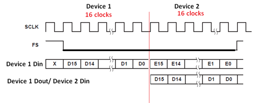
    Thanks for the post.  I think there may be some confusion regarding the serial communication interface.  For the TLV5630 device the main serial communication SPI channels are SCLK, FS, DIN, and DOUT.  The data format of the transaction is a 16-bit data word that consists of two parts: Address bits (D15-D12), and Data bits (D11-D0).  The complete register map is displayed on page 11 of the DS.  I've included a modified illustration of a register write in daisy mode:

    A total of 32 clocks are required to successfully write to both DACs at once.  Once FS (connected to both DACs) is pulled high the content of the shift register is moved to the DAC holding registers.  A logic 0 on the LDAC pin is required to transfer the content of the DAC holding register to the DAC latch, which will result in updating the DAC outputs.

    Please let me know if this answers your question.

    Best Regards,

    Matt

  • Hi, 

    Alright so the fs signal is for updating the registers, I first send 16 * 16 data bits and then I pull fs high?

    Thanks for your effort!

    Kevin

  • Hello Kevin,

    For two devices in daisy chain you would send a total of 32 unique data bits.  16 bits for the second device and the remaining 16 bits for the first device.  Once FS is pulled high these data bits will get latched into their respective DAC holding registers.  However, to fully update the DAC output, LDAC should be asserted with an active low signal that will update the DAC outputs with the voltage values stored in the DAC holding registers.

    Please let me know if you have any other questions.

    Thank you,

    Matt