This thread has been locked.

If you have a related question, please click the "Ask a related question" button in the top right corner. The newly created question will be automatically linked to this question.

noise on measuring TC with ADS1248

Other Parts Discussed in Thread: ADS1248

Hi everybody

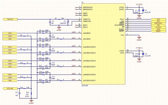
Recently I designed a board that measure Type K & J of TCs. My schematic is according to below figure. and sample rate is 5 S/S.

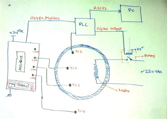
For testing of the operation of my board I use the below configuration.

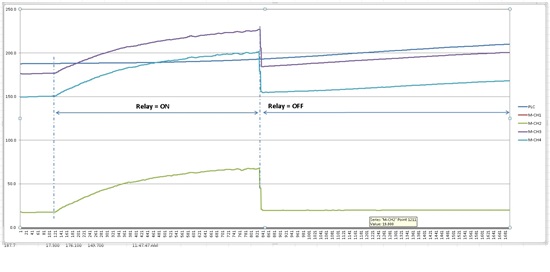
the result is according to the below figures

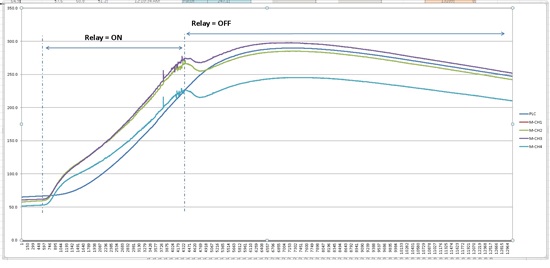
also if I put TC4 to the chamber

as you see on the above figures when we turn on the relay we have an offset and when we turn off the relay the offset is removed!!!

I do my best and test everything but I can't do anything.

can anybody help me??? please

best regard

Mahdi

  • Mahdi,


    First, why don't you describe more about your system. It would help to know what the configuration is for the first four registers. Also, it would help to know what your reference is and how you bias the thermocouples. For the graphs, what is the x-axis (what voltages are these? What is your expected value? I'd prefer to see the codes) and what is the y-axis (is this number of conversions? what data rate are you running? are you skipping any data reads?).

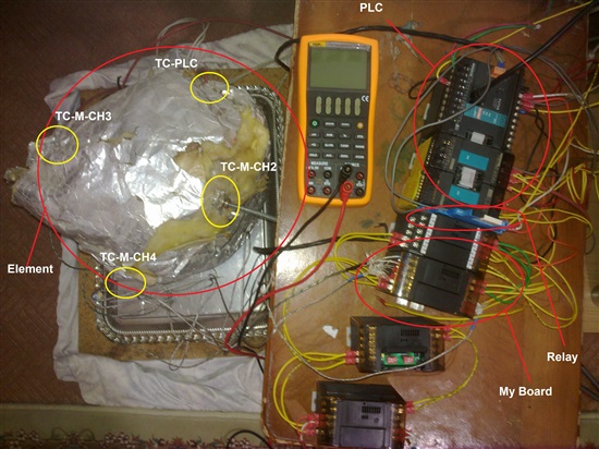
    For the drawing of the board you have, I think you'll need to describe more of it. What is enclosure you have around the heater? Maybe a photo might help. Are the relay and heater connected electrically to the board with the ADS1248?

    Based on the fact that the readings seem to affect TC2, 3, and 4, but not 1, all at the same time, I would guess that the problem is somewhere in the reference. By using the relay, the extra current is changing something in the reference value. If you have a precision digital multimeter, you can check the value. If you report the output codes, we might be able to see if this is a possibility.

    It's also possible that the relay/heater is coupling some sort of EMI into the circuit, but I think the reference is a more likely possibility.


    Joseph Wu

  • Hi Joseph

    thank you for your reply

    configuration bit is:

    CHAR1 = 0b00100101; CHAR2 = 0b01000101; CHAR3 = 0b00100000; Burnout_CS = 0b10000000;

            _ADS1248_REG.MUX0._MUX0     = CHAR1 | Burnout_CS;
            _ADS1248_REG.VBIAS._VBIAS     = CHAR3;
            _ADS1248_REG.MUX1._MUX1     = 0x38;
            _ADS1248_REG.SYS0._SYS0     = 0x30;        //PGA = 8, DOR = 5 SPS
            _ADS1248_REG.IDAC0._IDAC0     = 0x00;
            _ADS1248_REG.IDAC1._IDAC1     = 0b11111111;

    -for the graphs, the x-axis is time. (i mean that i store every conversion on the excel) and y-axis is temperature.

    -on the graphs I have 3 colored-line "PLC", "M-CH2", "M-CH3", "M-CH4",the value for "PLC" is my expected value.

    -data rate is 5 sample per second.

    -according to what i said, i don't connected any TC to channel 1 and on the graph it doesn't exist.

    the below picture can help:

    also part of my code is here:

                    if ( RTDorTC[ channel] == 0)                                {    /*TC*/
                        if ( _ADS1248._24bitADC == 0x7FFFFF)                    {    /*go to the next channel with BC*/
                            if ( ( Sensor_MAP & 0b00000001) == 0b00000001)       
                                 {    CHAR1 = 0b00110111 | Burnout_CS; CHAR2 = 0b01100111; CHAR3 = 0b10000000;}  
                            if ( ( Sensor_MAP & 0b00001000) == 0b00001000)        
                                 {    CHAR1 = 0b00100101 | Burnout_CS; CHAR2 = 0b01000101; CHAR3 = 0b00100000;}
                            if ( ( Sensor_MAP & 0b00000100) == 0b00000100)        
                                 {    CHAR1 = 0b00000001 | Burnout_CS; CHAR2 = 0b00000001; CHAR3 = 0b00000010;}
                            if ( ( Sensor_MAP & 0b00000010) == 0b00000010)        
                                  {    CHAR1 = 0b00010011 | Burnout_CS; CHAR2 = 0b00100011; CHAR3 = 0b00001000;}
                            ADC_RESULT._f[ 0] = 0.0;
                            _4x[ channel] = 0x8000;
                        }//if ( _ADS1248._24bitADC == 0x7FFFFF)
                        if ( _ADS1248._24bitADC != 0x7FFFFF)                    {
                            if ( TC_BCS_count == 0)                                {
                                if ( ( Sensor_MAP & 0b00000001) == 0b00000001)  
                                      {    CHAR1 = 0b00110111;              CHAR2 = 0b01100111; CHAR3 = 0b10000000;}
                                TC_BCS_count = 1;
                            }//if ( TC_BCS_count == 0)
                            else                                                {    /*go to the next channel without BC*/
                                A2T_TC ( );
                                if ( ( Sensor_MAP & 0b00000001) == 0b00000001)    
                                     {    CHAR1 = 0b00110111 | Burnout_CS; CHAR2 = 0b01100111; CHAR3 = 0b10000000;}
                                if ( ( Sensor_MAP & 0b00001000) == 0b00001000)    
                                     {    CHAR1 = 0b00100101 | Burnout_CS; CHAR2 = 0b01000101; CHAR3 = 0b00100000;}
                                if ( ( Sensor_MAP & 0b00000100) == 0b00000100)  
                                     {    CHAR1 = 0b00000001 | Burnout_CS; CHAR2 = 0b00000001; CHAR3 = 0b00000010;}
                                if ( ( Sensor_MAP & 0b00000010) == 0b00000010)    
                                     {    CHAR1 = 0b00010011 | Burnout_CS; CHAR2 = 0b00100011; CHAR3 = 0b00001000;}
                                TC_BCS_count = 0;
                            }//else
                        }//if ( _ADS1248._24bitADC != 0x7FFFFF)
                    }//if ( RTDorTC[ channel] == 0)
  • 1. You can try to set your TC to a Pricision Voltage Reference Point. Ext, Out put the internal reference. For TC work point. 2. Delay acquire dat when switch multiplexer & relay. Try to use the parameter calibrate the offset.
  • Mahdi,


    Looking at your setup, it's entirely possible that you have some EMI that is causing an offset. With so many wires you can radiate noise, and pick up any electromagnetic interference. I would guess that heater and relay currents are likely to cause the most problems because of their high currents. Since thermocouples are generally small voltages, it doesn't take much to add error.

    To help get rid of this, physically separating components may help. That would be to move the sensor board away from the other electronics that may radiate energy that could be picked up by the sensors. I would also try to twist the thermocouple wires so that the loop area is smaller and picks up less radiated energy as an antenna.

    Try some of these things. I also mentioned quite a few other things I'd like to see in my previous post, about the data and the magnitude of the error.


    Joseph Wu