This thread has been locked.

If you have a related question, please click the "Ask a related question" button in the top right corner. The newly created question will be automatically linked to this question.

ADS1256, DRDY continuously flows after SDATAC command

Other Parts Discussed in Thread: ADS1256

Hi All,

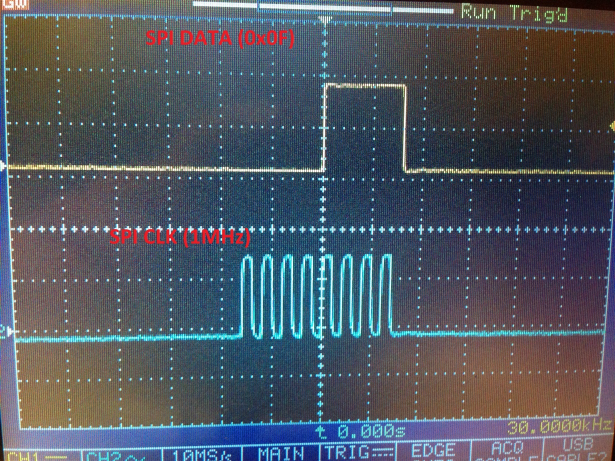
I try to stop continuously data read mode in ADS1256. in my code I continuously send SDATAC command to the ADC (0x0F command). SPI CLK = 1MHz.

Here is oscillogram #1 (shown SPI data and CLK flow to the ADC), as you can see I send 0x0F command (SDATAC)

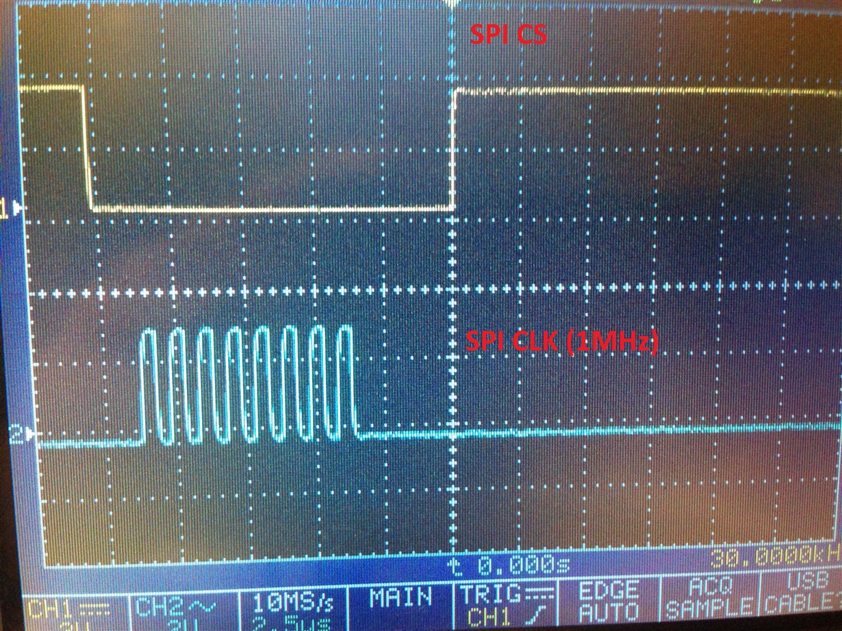
Here is oscillogram #2 (shown SPI CS and clock identical to figure #1)

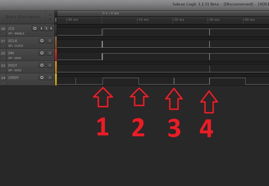
Here is oscillogram #3 (shown CPI CS as in figure #2 and DRDY signal flows from the ADC)

As you can see from figures above, I wait until DRDY became HIGH and after start SPI transaction.

My questions are:

  1. why DRDY after receive command SDATAC anyway read data continuosly?
  2. Why DRDY is HIGH only about 3uS as result SPI transaction lasts more than the period
  3. How to stop continuosly receive DRDY, as my only command is SDATAC?

Thanks a lot for any advice, I'm stuck on the issue

  • Hi Vasiliy,

    Please pardon the delayed response. To answer your questions:

    1. The SDATAC command will not affect the behavior of /DRDY.
      /DRDY will pulse to show that a conversion has completed. The only way to halt conversions is to put the ADS1256 into the standby or power-down modes. Otherwise the ADC will be constantly converting.

      The purpose of the SDATAC and RDATAC commands is only to change the way you read data after a conversion.
      (SDATAC is not the same as a STOP command, that is used on some of our other devices)

    2. Refer to page 27 in the datasheet, /DRDY will pulse high like this to show that data is being updated (when you have not already read the data). Normally /DRDY would reset back to a HIGH state after your read out all 24-bits of data.

    3. Send the STANDBY command or set the /PDWN pin LOW to stop data conversions (which in turn disables /DRDY from going LOW). This is optional - you may also simply ignore the /DRDY pulse when you do not require data.

    Best Regards,
    Chris

  • Hi Chris,

    Thanks for reply, anyway any reply/idea increase my understanding of the ADC.
    Well, actually a root of the post was imposibility of reading/write data from/to internal ADC's registers (I read several topics on it here and your replies too). So, my thought the issue was the reason. At the moment I can read/write registers. How I fix it? I start any SPI activity since falling edge of DRDY.

    Anyway - thanks for reply
  • Hi Vasiliy,

    So you are correctly reading and writing to the device registers now?

    The initial order that you send SPI commands is important:

    1. The first command you should send is SDATAC. (This takes the device out of read continuously mode - i.e. out of RDATAC mode into SDATAC mode)
    2. Then you should be able to Read/Write to the devices registers (you can only do this in SDATAC mode).
    3. After configuring the registers, you should restart the ADC conversion by sending SYNC & WAKEUP commands.
    4. You may then proceed back to RDATAC mode OR remain in SDATAC mode (and use the RDATA command to retrieve data).

    Best Regards,
    Chris

  • Yes, I can read registers correctly now.

    I don't use continuous reading mode, so my sequence seems like:

    #1(your item 1)
    #2(your item 2)
    #3(your item 3)
    #4 change MUX register value
    #5 SYNC&WAKEUP
    #6 wait until falling edge of DRDY
    #7 RDATA command
    #8 read 3 data bytes from ADC

    after, I repeat steps from 4 to 8

  • Hi Vasiliy,

    That sequence should be fine! (Just be mindful that some commands will require a short delay before you can send another command. See timing requirements "t6" and "t11" on page 6 of the datasheet).

    Since you are multiplexing, you could speed up your communication slightly by following the command sequence shown in figure 19 of the data sheet. I posted some ADS1256 Example Code of how to do this with the corresponding logic analyzer data on this related E2E thread: http://e2e.ti.com/support/data_converters/precision_data_converters/f/73/p/338399/1182307.aspx#1182307. The logic analyzer data can be opened in the Saleae software (available here: https://www.saleae.com/downloads).

    Best Regards,
    Chris

  • Yes, I already got the time delay requirements between commands from my experiments.

    And yes, I already saw your code from the topic last week, very helpfull, thanks!
  • Hi Chris,


    I have extra question in regard with DRDY. I've found on the forum (in topic your participated in) logic analyzer file (Saleae, ADS1256_MMB3_Multiplexing.logicdata link). Here is screen shot of repeatedly continuos process of MUX switching from channel to channel and data read from a ADC.

    in the point #1 there are MUX switch + read of previous data.

    My question is, why next data read (+MUX switch) is in DRDY toggle in pont #4, why not point #2 or #3?

    Thanks!

  • Hi Vasiliy,

    Great question and good find! Actually, I could have read the data at point #2 without a problem. Sorry for the confusion!

    I waited for 3 conversion cycles in case the digital filter was not settled; however, the digital filter settles in 1-cycle when multiplexing like this. Therefore, ignoring /DRDY at points # 2 & 3 was unnecessary.

    You would need to ignore a few /DRDY falling edges only if you were continuously converting (without switching MUX channels) at a data rate of 7.5kSPS or higher (see table 15). The ADS1256 is not single-cycle settling for data rates great than 7.5kSPS; however when issuing the SYNC command, /DRDY will stay high longer to indicate that the digital filter has not settled in this case.

    Best Regards,
    Chris

  • Ok, got it, thanks!