This thread has been locked.

If you have a related question, please click the "Ask a related question" button in the top right corner. The newly created question will be automatically linked to this question.

ADS1191 Small and Noisy Signal

Other Parts Discussed in Thread: ADS1191, ADS1192, ADS1291

I am working on a custom ECG board using the ADS1191 and am having some issues with the signal. Eventually I plan on using dry electrodes, but for now I am using two gel electrodes on the chest (Lead I).

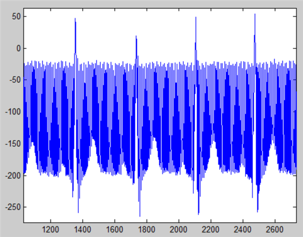
There is more 60 Hz noise than I was expecting when using the RLD. Additionally, the signal level seems very low.

The sample rate is set to 500 sps and the gain was set to 12 (the max).

ADS1191_write_register(0x02, 0xA0);		// Using internal reference, write CONFIG2(0x02) = 0xA0
ADS1191_write_register(0x01, 0x02);		// Set data rate to 500SPS, CONFIG1(0x01) = 0x02
ADS1191_write_register(0x04, 0x60);		// Set gain to 12 on ch1

It is also strange to me that the noise is not centered around the ECG signal. So I guess I have two questions:

1. Why is the amplitude so small? The gain is set to the maximum value, the integrated ADC has 16-bits of resolution, and the ECG R-peak has an amplitude of about 300. This does not seem right. Am I doing anything wrong? This could become a serious issue when I move to dry electrodes.

2. Does anyone have any insights into the 60 Hz noise? I have verified that it is 60 Hz noise in MATLAB. The only analog circuitry between the electrodes and AFE is a simple low-pass filter (47k and 47pF). This matches the evaluation board schematic for the ADS1192. It seems like there may be an issue with DC biasing on the inputs.

Thank you for your help!

  • Nicholas,


    I am moving your post to the correct forum.

  • Thank you Amy. For future reference, the "Filter forums by" search must have suggested the incorrect forum for the ADS1191.

  • Hi Nicholas,

    Thank you for your post!

    1. The amplitude of the ECG signal seems ok to me. A 16-bit converter with a 2.4-V reference and PGA = 12 V/V has an LSB (least-significant bit) size of (2*2.4V/12V/V) / (2^16 - 1) = 6.15 uV. An R-peak of about 300 codes would translate to a 1.85 mV input, which I believe is within a normal range for ECG. Is that what you were expecting? What are you using for a signal source?

    2. 60Hz noise is generally filtered out in the digital domain. This can be accomplished either by implementing a high-order notch filter in software, or by slowing down the data rate of the ADS1191. The digital sinc-3 filter in the ADS1191 has a -3dB bandwidth of 0.262*fDR. At 125 SPS, your bandwidth would only be ~32Hz. ECG signals range from 0.05Hz up to 150Hz, so the second option may not be useful if you need the full ECG bandwidth.

    The low-pass filters you see on our EVM have a cutoff frequency of ~72kHz and primarily serve as anti-aliasing filters. Realistically, this cutoff could be set even lower (i.e. 1kHz to 10kHz) to provide even more attenuation at the modulator frequency (fmod = 128kHz in the ADS1191).

    Best Regards,

  • Ryan, thank you for your response.

    #1 does not make sense to me. Why sell an AFE with an integrated ECG front-end with a 16-bit ADC and a maximum gain of 12? I have all of this resolution that is not getting used because the ECG signal is not being amplified as much as it could/should be. You may want to rethink this for future ECG AFE designs.

    Do you have any suggestions on how to handle this issue? Otherwise, I will need to either design my own instrumentation or look elsewhere.

    #2. Understood.

    Thank you again for getting back to me!
  • Hi Nicholas,

    Not all customers require such high resolution for their application, so the ADS1191 was designed to meet a lower price point with similar performance and features as its ADS1291 counterpart.

    With the same 2.4V reference and a gain of 12V/V, the 24-bit ADS1291 would achieve a resolution of 23.8nV/code, more than two orders of magnitude better than 6.1uV/code in the ADS1191. However, to your point, it is still highly unlikely (and probably impractical) to use the entire full-scale range of the ADC in ECG applications.

    Take a 2mV input, for example, with the same configuration as above. In the ADS1191, 2mV would represent 328 codes or 0.5% of 2^16 possible codes. Conversely, for the ADS1291, 2mV would represent 84,033 codes or 0.5% of 2^24 possible codes. Using the full-scale range of the ADC is not necessary to achieve the resolution that you need in your application.

    To improve the resolution with a 16-bit converter, you could add an external gain stage like you mentioned, or you could decrease the size of the reference voltage and provide it externally. Either option has the potential to introduce added noise and error in your measurements, but it can certainly be done.

    We appreciate your inputs. :)