This thread has been locked.

If you have a related question, please click the "Ask a related question" button in the top right corner. The newly created question will be automatically linked to this question.

ADS1230 POWER SECTION ISSUES

Other Parts Discussed in Thread: ADS1230

Hello Bob;

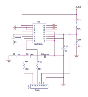
 I am having some issues in the power section of ADS1230. The resistor R11 is 1E - 0805 package and C11 is 470uf /16V capacitor. The R11 resistor is burn out (dead) in most cases when i connect the loadcell, is this problem due to power rating of the resistor.

Secondly is there any  special no clean flux must be used for better result. Will RF800 liquid flux be suitable, its low solid no clean flux (5% solid).

Thank You

  • Hi Dhinesh,

    It is quite possible that your design is marginal.  For example, the 470uF cap will act as a DC short for a period of time when you first power up.  This initial charge time will be extended if a large enough load is added to the same point (such as the load cell). Even though the actual time that the cap acts as a short (or near short) is small, the current running through the resistor will be quite large and will degrade the performance of the resistor.  The resistor is most likely 1/8 W, so the maximum current for a DC short at 5V is 25mA.  You will have to look at the datasheet for the resistor to see what peak current and duration are acceptable. 1206 size resistors are usually 1/4 W and this may be more suitable, but perhaps 1/2 W or larger capacity may be required.

    As to flux, there are a couple of things to consider.  One is the amount of flux applied and the other is whether or not it has been fully activated.  No clean flux is very agressive as a fluxing agent.  If you apply a lot of flux and it is not completely activated you will have a problem.  Even if the flux has been completely activated, you may still have a problem due to the residue acting as a leakage path if excessive flux is applied. No clean flux works best in a reflow environement where the amount of flux and reflow temperatures are well controlled.  I personally have found that I still have to clean the boards when hand soldering and using no clean flux.

    Best regards,
    Bob B


  • Hi Bob;

    I need some clarifications, in my earlier circuit (posted above) R11 resistor is 1E and C11 is 470uf/16V capacitor.

    since its ratiometric measurement why cant we connect +5VDC (VCC) directly to Analog power section AVCC and REF pins, why should we need to add a resistor and capacitor to separate digital and analog power section.

    kindly advise.
  • Hi Dhinesh,

    The use of the filter resistor is optional.  The resistor is not a requirement.  Some people use switched mode power supplies that can be very noisy.  If you use a switching supply, I would suggest that you regulate from the switching supply voltage to 5V using a low noise, LDO linear regulator.

    Of greater concern is the PCB layout when trying to minimize noise.  You need to make sure that all digital circuitry and traces are not crossing into the analog section of your board.  Also, it is important to have a good ground plane as opposed to just ground traces on your board for best performance.

    As far as the ratiometric measurement is concerned, you must also consider the noise, timing, and the phase relationship due to filtering of the analog input that may be different than the reference input.  All things being equal, the noise and drift of the measurement should cancel.  However, any noise picked up from wiring connections, or changes due to analog input filtering (with respect to the reference input) will disrupt the ratiometric measurement.

    Best regards,

    Bob B