This thread has been locked.

If you have a related question, please click the "Ask a related question" button in the top right corner. The newly created question will be automatically linked to this question.

ADS1299 Device ID get over SPI

Other Parts Discussed in Thread: ADS1299

Hi,

I am using software SPI in ATMEGA1281, built in module of MikroC PRO for AVR.

I am using following code, kindly let me know where I am making the mistake, please.

Thanks in advance with best regards.


sbit Chip_Select at PORTA5_bit; // Software SPI Chip Select
sbit SoftSpi_CLK at PORTA6_bit; // Software SPI CLK
sbit SoftSpi_SDI at PINA7_bit; // Software SPI Data In
sbit SoftSpi_SDO at PORTG2_bit; // Software SPI Data Out

sbit Chip_Select_Direction at DDA5_bit;
sbit SoftSpi_CLK_Direction at DDA6_bit;
sbit SoftSpi_SDI_Direction at DDA7_bit;
sbit SoftSpi_SDO_Direction at DDG2_bit;

void main()
{
int i;
unsigned short out_spi;

DDRA = 0x7F; // set direction to be output at Port A
DDRB = 0xFF; // set direction to be output at Port B
DDRC = 0xF0; // set direction to be output at Port C
DDRD = 0xFF; // set direction to be output at Port D
DDRE = 0xFF; // set direction to be output at Port E
DDRG = 0xFF; // set direction to be output at Port G

PORTB = 0x00; // PORTB Output
PORTD = 0x40; // PORTD Output
PORTE = 0x00; // PORTE Output
PORTG = 0x00; // PORTG Output

UART2_Init(115200); // UART Initialization at 115200 Baud Rate
Soft_SPI_Init(); // Init Soft_SPI
Delay_ms(20000); // Delay of 2second

PORTC5_bit= 1; //CLKSEL=1 for internal Clock of ADS1299
Delay_ms(1000);
PORTC7_bit= 1; //START of ADS1299 set High

PORTA0_bit= 1; //PDWN of ADS1299
delay_ms(1200);

/* For Sequence detection*/

for ( i=0; i<10; i++)
{
UART2_Write_Text("A");
delay_ms(500);
UART2_Write_Text("B");
delay_ms(500);
UART2_Write_Text("C");
delay_ms(500);
}

PORTA5_bit= 0; // Chip Select of ADS1299
Soft_SPI_Write(0x88); //Data Mode
delay_ms(15);
PORTA5_bit= 1;
delay_ms(200);

/* ADS1299 Reset Setting*/

PORTA5_bit= 0; // Chip Select of ADS1299
Soft_SPI_Write(0x60); //Reset
delay_ms(15);
PORTA5_bit= 1;
delay_ms(200);

/* SDATA & RREG*/

PORTA5_bit= 0; // Chip Select of ADS1299
Soft_SPI_Write(0x88); // SDATA ADS1299
delay_ms(15);
PORTA5_bit= 1;

PORTA5_bit= 0;
Soft_SPI_Write(0x04); // RREG ADS1299
Soft_SPI_Write(0x00); // Ask for 1 Byte
delay_ms(15);
PORTA5_bit= 1;

do
{
PORTA3_bit= 1; // Debug LED1
PORTA1_bit= 0; // Debug LED2
Delay_ms(500);

PORTA5_bit= 0;
out_spi = Soft_SPI_Read(0x00); // Read ADS1299 ID
delay_ms(15);
PORTA5_bit= 1;

UART2_Write(out_spi);
delay_ms(5);

PORTA3_bit= 0; // Debug LED1
PORTA1_bit= 1; // Debug LED2
Delay_ms(500);

} while(1); // Endless loop
}

  • Hello Ghalib,

    I am not familiar with the ATMEGA1281 or the AVR architecture in general, but I can make a few suggestions based on my experience communicating with our parts via SPI with other microcontrollers. First, how does the SCLK work with the SPI module on this microprocessor? For some microprocessors, SCLKs are only generated when data is being written from the master. In your program, you write the two first opcode bytes of the RREG command which includes the address and number of registers you wish to read, then you wait a while and pull CS high. Does the microprocessor continue to send another 8 SCLK periods for the read data to be shifted out before CS is pulled high? If not, the interface will be reset without actually shifting out the register contents.

    In addition, you make one call to the Soft_SPI_Read function to read the data. How is new SPI data stored on the processor? Is there a receive FIFO which holds a certain amount of data until each point is read individually by the processor, or does it simply overwrite old data any time a new SPI transaction shifts in new MISO data. If the SPI MISO data is stored in a FIFO, you may have to read out all of the "don't care" data that was generated from all of your other SPI commands, including the first two RREG opcodes, before you will read the register contents (all of this is assuming there are enough SCLKs to shift out all the register data).

    I think the first step in your debug process should be to connect your SPI bus to an oscilloscope or logic analyzer, look at what is happening during your RREG operation, and compare it to the timing which is illustrated on page 38 of the ADS1299 datasheet. Seeing what is happening on the bus should give you an idea of what may be going wrong. If you look at it and you still can't figure out what is wrong, post some oscilloscope screen capture images here so we can debug together.

    Regards,
    Brian Pisani
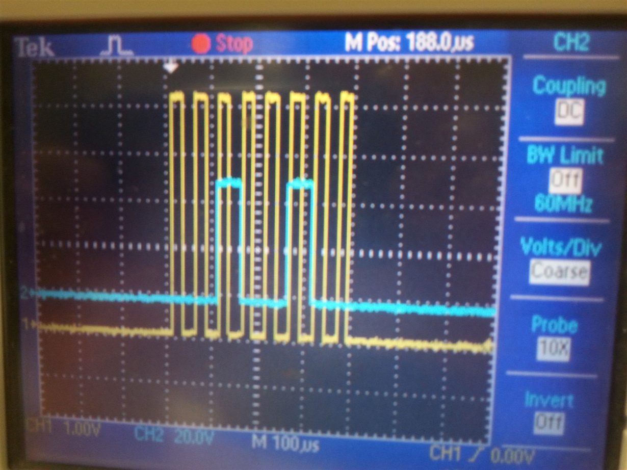
  • Thanks a million Brian, I have checked the SPI over oscilloscope its working perfectly fine shown below SPI Dout + CLK for 0x24.  My Software SPI is working at 20Khz and sends out LSB first, is it OK?

  • Hey Ghalib,

    What is the purpose of that command? Are you attempting to read the data stored in register 0x04? If that is the case you need another byte to specify the number of registers you wish to read and enough SCLKs following that to shift out the data you expect. For example, look at the following binary representations of the data lines during a valid read of the ID register (Xs indicate don't cares):

    MOSI: 0100 0000 0000 0000 XXXX XXXX
    MISO: XXXX XXXX XXXX XXXX DDDD DDDD

    The first MOSI byte is the REG opcode and the address of the ID register. The second byte is the (num registers - 1). The final MOSI byte is a byte of don't care data that will be sent while the register data is being sent out by the slave. The entire transaction will last 24 SCLK periods, during which time CS must remain low. If the SPI bus looks exactly like that during a register read then the correct data should be obtained. Let me know if the output on the SPI looks that way and you still cannot obtain the register data.

    Regards,
    Brian
  • Hi Brian,

    Thanks for your help.

    The data on oscilloscope is not a  command but it is only picture I taken during checking the SPI. I am doing the exact same sequence of command you showed for MOSI & MISO but ID is not coming correctly . This is my schematic I am using if you can kindly have a look on this too, I might have made some mistake. I have made the reset pullup high with MCU

  • Hay Ghalib,

    Your schematic looks good. I know you said the RESET pin is pulled high, but what is the status of the PWDN pin? That must also be pulled high for the device to function correctly. Does the device seem like it is in a working state otherwise? Does DRDY pin pulse at the expected datarate when the START pin is held high?

    Brian
  • Hi Brian,

    Thanks a million. PWDN pin is set to high. I am using internal oscillator after setting START pin to high DYRY should occur at the rate of 2.048MHz/8192=250 Hz but when I see it on oscilloscope it not appearing at constant rate it occurs up 125Khz , with varying frequency.

    Can you guide me what can be possible problem or mistake I am making? 

    I have changed the code , given below and now it is reading the right ID but not every time I want to read.

    Regards,

    Ghalib

    Code:


    sbit Chip_Select at PORTA5_bit; // Software SPI Chip Select
    sbit SoftSpi_CLK at PORTA6_bit; // Software SPI CLK
    sbit SoftSpi_SDI at PINA7_bit; // Software SPI Data In
    sbit SoftSpi_SDO at PORTG2_bit; // Software SPI Data Out

    int i;
    char out_spi;

    char Soft_SPI_xfer (char SPI_byte)
    {
    unsigned char SPI_count; // counter for SPI transaction
    SoftSpi_CLK = 0b0; // set SCK low

    for (SPI_count = 8; SPI_count > 0; SPI_count--) // single byte SPI loop
    {


    if (SPI_byte & 0x80) // put current outgoing bit on MOSI
    SoftSpi_SDO = 1;
    else
    SoftSpi_SDO = 0;
    SPI_byte = SPI_byte << 1; // shift next bit into MSB

    SoftSpi_CLK = 0b1; // set SCK high

    SPI_byte |= SoftSpi_SDI; // capture current bit on MISO
    SoftSpi_CLK = 0b0; // set SCK low

    }
    return (SPI_byte);
    } // END Soft_SPI_Read

    void main()
    {


    DDRA = 0x7F; // set direction to be output at Port A
    DDRB = 0xFF; // set direction to be output at Port B
    DDRC = 0xB0; // set direction to be output at Port C
    DDRD = 0xFF; // set direction to be output at Port D
    DDRE = 0xFF; // set direction to be output at Port E
    DDRG = 0xFF; // set direction to be output at Port G

    UART2_Init(115200); // UART Initialization at 115200 Baud Rate
    // Soft_SPI_Init(); // Init Soft_SPI

    PORTB = 0x00; // PORTB Output
    PORTD = 0x40; // PORTD Output
    PORTE = 0x00; // PORTE Output
    PORTG = 0x00; // PORTG Output


    PORTA3_bit = 0b1;
    PINA1_bit = 0b1;
    Delay_ms(20000); // Delay of 2second

    PORTC5_bit= 0b1; //CLKSEL=1 for internal Clock of ADS1299
    Delay_ms(1000);
    PORTC7_bit= 0b1; //START of ADS1299 set High

    PORTA0_bit= 1; //PDWN of ADS1299
    delay_ms(1200);

    // For Sequence detection
    for (i=0; i<10; i++)
    {
    UART2_Write_Text("A");
    delay_ms(100);
    UART2_Write_Text("B");
    delay_ms(100);
    UART2_Write_Text("C");
    delay_ms(100);
    }

    do
    {
    PORTA3_bit= 0b1; // Debug LED1
    PORTA1_bit= 0b0; // Debug LED2
    Delay_ms(100);

    UART2_Write(0xAA);
    delay_ms(15);

    Chip_Select = 0b0; // Chip Select of ADS1299
    Soft_SPI_xfer(0x11); // SDATA ADS1299
    delay_ms(1);
    Chip_Select = 0b1;

    Chip_Select = 0b0; // Chip Select of ADS1299
    Soft_SPI_xfer(0x06); //Reset
    delay_ms(1);
    Chip_Select = 0b1;
    delay_ms(2000);

    // SDATA & RREG

    Chip_Select = 0b0; // Chip Select of ADS1299
    Soft_SPI_xfer(0x11); // SDATA ADS1299
    delay_ms(1);
    Chip_Select = 0b1;

    Chip_Select = 0b0; // Chip Select of ADS1299
    Soft_SPI_xfer(0x12); // RDATA ADS1299
    delay_ms(1);
    Chip_Select = 0b1;

    Chip_Select = 0b0;
    Soft_SPI_xfer(0x11);
    Soft_SPI_xfer(0x20); // RREG ADS1299
    Soft_SPI_xfer(0x00); // Ask for 1 Byte
    out_spi = Soft_SPI_xfer(0x00); // Read ADS1299 ID


    out_spi= out_spi & 0x0F;
    if (out_spi == 0x0E)
    UART2_Write(out_spi);
    delay_ms(1);
    Chip_Select = 0b1;

    PORTA3_bit= 0b0; // Debug LED1
    PORTA1_bit= 0b1; // Debug LED2
    Delay_ms(100);

    } while(1); // Endless loop
    }

  • Hi Ghalib,

    The DRDY pulse should be very constant so your experience suggests that there could be an issue with the board or the power supplies. What voltage supplies are you using? Do they appear constant when you measure them?

    Brian
  • Hi Brian,

    Thanks a million. I was using AC- DC adapter which provide 3.23V and powers to ADS1299 is 2.5V and -2.26V to -2.27V . I have also tried the circuit on 3.7V battery its quite the same.

    It this scenario OK for proper working on ADS1299?

    Regards,
    Ghalib

  • Ghalib,

    I'm assuming that the 3.23 V supply is the digital supply and the bipolar supplies are for AVDD and AVSS. Is that correct? If that is the case then that is a valid power supply configuration. Is the voltages that you stated their measured level? Do you notice them unexpectedly falling or drooping at all?

    Regards,
    Brian Pisani
  • Thanks again Brian,

    The main input to board is 3.23V  and AVDD is 2.5V & AVSS is -2.26V (MCU is operating at 2.67V ). It is measured voltages and there is not unexpected drop at all.

    One thing I want to tell you that MCU is measuring the right ID of ADS1299 once in 12-20 attempt.

    Regards,
    Ghalib

  • Ghalib,

    I think we need to first ensure that the device is in a normal operating state before we debug your register read routine. Can you post a picture of the oscilloscope with the DRDY pin pulsing at the very fast frequencies? The maximum datarate for this device is 16 kSPS so DRDY pulsing with a frequency of 125 kSPS is definitely a problem.

    Brian
  • Hi Brian,

    Thanks a million for you guidance.

    you can the video of DRDY captured at following link.

    drive.google.com/.../view

    I have changed the scope and found that it varies upto 83Hz .

    I have two boards and both are behaving same .

    Ghalib
  • Hey Ghalib,

    It's unclear to me from the video what is happening. Are you triggering on the edge of the DRDY pin but it's moving around too much to see any consistent pattern? What does the scope say when you measure the negative edge pulse width for that scope channel?

    Regarding the code you posted previously, what is the function of the hex 0x11 that you shift to the ADS1299 before the RREG opcode? That will probably cause the device to decode the wrong opcode before it receives the RREG command.

    Brian
  • Hi Brian, 

    Thanks a million. My apologies I should have turned off the channel 2, in cyan colour. I have used channel 1, in yellow colour, for measurement. The DRDY signal is not showing any consistent behaviour.  I will upload a new measurement by today. 

    I am using 0x11 for SDATA  command, behaviour is quite the same if I remove it too.

    Regards,

    Ghalib

  • Hello Ghalib,


    I'd really appreciate it if I could see exactly what was going on there. Make sure the scope is triggering on the negative edge of the DRDY pin and try to zoom it in as much as possible so I can see the different frequencies that it's occurring at. Even with the yellow it was sort of hard to tell. Maybe instead of a video a couple of pictures of the different frequencies would be more helpful. I'm sorry to be so picky; I just want to have a very specific grasp on what is happening so when I consult the designer for the part I can have a concrete list of symptoms.


    To be sure we're on the same page with the SDATAC command, I was referring to the one that comes here:

    Chip_Select = 0b0;
    Soft_SPI_xfer(0x11);
    Soft_SPI_xfer(0x20); // RREG ADS1299
    Soft_SPI_xfer(0x00); // Ask for 1 Byte
    out_spi = Soft_SPI_xfer(0x00); // Read ADS1299 ID


    That SDATAC command will definitely throw things off. Even if you can’t get the read to work completely right now, I’d recommend taking it out to save yourself the future headache. Also, what happens to shifted in SPI data that isn’t read by the processor? Is it just overwritten by the newest data?


    Regards,

    Brian

  • Hi Brian,

    Thank for you help. I like your preciseness and will do as you mentioned and send you the data as soon as I get back my board from workshop.
    I will remove the SDATA command from code too.

    Regards,
  • Ghalib,

    I appreciate your patience with this.

    Brian
  • Hey Ghalib,

    That DRDY is definitely valid. Its negative edge occurs at the expected data rate. At this point I only see two sources for this problem. Either the SPI command or timing is not what the device expects, or your microcontroller stores SPI data in a way that is inconsistent with your understanding. You said you are reading the correct output every few reads, but in your code you are ANDing out the first four bits of the data you read back. In that case, I’m not totally convinced that the data you are eventually sending to your PC was the valid data read from the ID register.

    Let’s try a few things to determine the source of the problem. First, trigger a single scope capture on your SPI transaction where you try to read the device ID, take a photo of it, and post it here. Track SCLK, CS, DIN, and DOUT. If we look at the timing and the bits on the scope and see that they are the correct values we expect and you are not seeing the same value on your PC, then the issue is in software. If we see that you are sending the correct command and have the correct timing, but we see on the scope that the data that is getting returned by the device is not valid, then we can explore other possible problems.

    Regards,
    Brian
  • Hi Brian,

    Thanks a million for your reply. I have capturing the same data as in MCU from ADS1299. I am using software SPI and it is not working at exactly 1MHz, can it be the possible problem? I am asking you as I sending Clk from MCU to ADS1299 so I am view that it can't be a problem.

    I didn't get your point about ANDing the first four bits as datasheet states that XE (x=don't care) is ID of the device, am I right?

    Regards,
    Ghalib

  • Hi Ghalib,

    I was concerned that perhaps your timing was not exactly correct so if I could see the entire transaction over SPI, that would be helpful in determining your problem. My point with the ANDing of the ID register contents, is that if the data you are reading is garbage, then there are a greater number of possible words that could be processed whose final four bits are all ones but whose preceding bits are not consistent. I would recommend reading all the bits to ensure that the entire word is read the same way each time.

    Regards,
    Brian Pisani
  • Hi Brian,

    I was able to figure out the issue as it was the problem with reading of data, as you suggested, with reference to settling time. I able to get the data correctly but just adding a "NOP" delay.

    Sorry could update you earlier.

    Thanks for all your help and guidance.

    Regards,
    Ghalib