This thread has been locked.

If you have a related question, please click the "Ask a related question" button in the top right corner. The newly created question will be automatically linked to this question.

ADS1299 EVM CMRR and SNR measuring at default condition

Other Parts Discussed in Thread: ADS1299

Hello, 

  I'm having trouble figuring out if measured CMRR / SNR is meaningful data and what does it mean ... ? Can you guy help me out ??

Here is how I set. I'm using bi-polar power supply set-up (+-2.5V), and Ain+ signal through header, VCM drives SRB1 (which is JP25(5-6) ), and all other settings are set to factory default. 

   BIAS_ELEC : 0V, then SRB1 = LOW (switch open)

   REF_ELEC : 0V

   BIAN_IN : X (open)

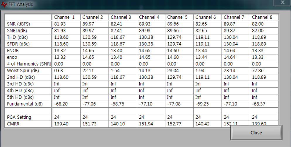
Then, I'm getting as below.

Here are questions.

1. For SNR ("signal"-"Noise" Ratio), how did EVM measured "signal" ? 

2. Is measured SNR meaningful (I doubt, because I left all electrodes open, no signal input) ? 

3. What about CMRR ? (I also doubt the number, for same reason that I left all electrodes open)

Thank you.


  • Hey Jason,

    Great questions! The EVM finds the signal by taking an FFT of the output data, finding the largest non-DC frequency component and labeling that bin as the "signal". To measure SNR, it takes the amplitude of that bin and a few bins around it (leakage due to windowing) and divides it by the mean frequency component amplitude. That number is converted to decibels and is displayed to the user. If there is no applied signal, that number is basically meaningless.

    The CMRR is calculated using the input voltage box on the FFT tab in the EVM. The voltage that you put there should be the input common mode amplitude that you are applying. Input your common mode signal to the shorted inputs of your acquisition channel. Then, using a similar method as described above, the EVM will find the common mode signal amplitude from the FFT, divide the full scale output amplitude by the common mode signal amplitude, and convert to decibels. You must enter the common mode input on your own because otherwise there would be no way for the EVM to know what the common mode signal amplitude was during any given acquisition. Again, however, if the signal is not being actively driven, that analysis in the table is essentially meaningless.

    Regards,
    Brian Pisani
  • Thank you so much Brian, 

    Even I still have some doubt, I think I'm getting meaningful numbers.

    Here is how I did, 

    1. Set bi-polar power supply (+-2.5V)

    2. Removed jumpers 5-36 of J6

    3. Removed all jumpers (1-2) (3-4) (5-6) of JP25

    4. Reference signal is directly feed to SRB2, with ground to waveform generator (SRB2 switch closed to route reference signal to AinP)

    5.  signal is driven to AinP passively w/ waveform generator frequency sine-wave 1Hz, amplitude 200mV (to channel 1 and 8 for simplicity)

    So, SRB1 becomes don't care, SRB2 drives positive input to PGAs, artificially generated signal goes into negative input to PGAs. All other settings left as factory default. Then, I'm getting result as below. 

    SNR ~86 for channel 1 and 8 seems not bad for passively driven signal and compared to ADS1299 chip specification, but I still get some unknown noise @ 70Hz.

    I'm thinking to apply high-pass filter on output of waveform generator (before applying to EVM), but I'm not sure if I'm doing things right.

    And, I'm looking at Figure 34 of ADS1299 EVM User's Guide (page. 31), it describes FFT analysis of "Input short condition" , does "input short condition" means externally short (shorting positive and negative input of PGAs) ? OR some register setting (Device noise) ?

    It's confusing if that described SNR represents "internal" signal-noise ratio.. ?

    I really appreciate for your help. Thank you,


  • Hi Jason,

    I misinterpreted you last post. If you are driving the ADC channels through the SRB pins, then the analysis will be meaningful. For your question about Figure 34 in the user's guide, the inputs are shorted internally to perform that analysis. However, the intention of Figure 34 is simply to familiarize the user with that particular display in the UI, not to provide meaningful example data. In fact, the FFT analysis algorithm that is used ignores the DC component, which one would imagine is the signal component when the inputs are shorted.

    Regards,
    Brian
  • For the first post, I was just letting all inputs open, and SRB1 SRB2 be at default setting. I came up with different setting after your reply. Thanks Brian! It helped me a lot to have better understanding on ADS1299 EVM !