This thread has been locked.

If you have a related question, please click the "Ask a related question" button in the top right corner. The newly created question will be automatically linked to this question.

ADS1299: 250 uVpp noise floor of unknown origin

Other Parts Discussed in Thread: ADS1299, ADS1294

Hello,

I am getting 250 uVpp gaussian noise at all channels, even when shorting inputs to ground and using the configuration which gives the lowest noise levels (G=24). I have no idea why this is happening, so I will give some details about the circuit I designed so as to rule out some possibilities:

-I am using integrated SMD voltage regulators from Texas Instruments and other SMD components in a relatively small design (5x5 cm, dual layer)

-I am using batteries to supply the circuit with power.

-I separated the analog and digital grounds and they only touch at one point in the circuit.

-I hand soldered all the components. (could a little bit of excess lead be an issue?)

-An arduino is used to send data to the PC.

-I tested the device with 100 mVpp sine waves and square waves and there was no problem in visualizing them on the PC, but the noise was still present.

Would you have any idea as to why this noise is present? I can post more details of my circuit if necessary.

Thanks in advance

Pablo

  • They Pablo,

    How certain are you that the noise is truly Gaussian? Have you analyzed it in the frequency domain? One of the most common sources of noise in medical applications is power line parasitics. If you were to view data in the frequency domain, it would be present as a peak at either 50 or 60 Hz, depending on your region.

    Regards,
    Brian Pisani
  • Hi Brian, 

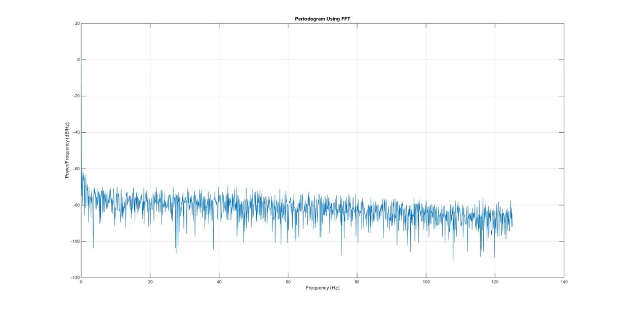
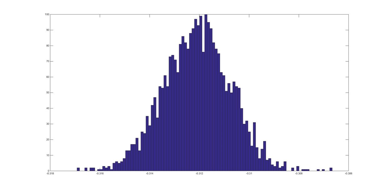
    I have plotted it's histogram and Power spectrum  (figures 1 and 2). I have tried to avoid power line noise by using an unplugged laptop and moving away/turning off any other electronics and fluorescent lights nearby.

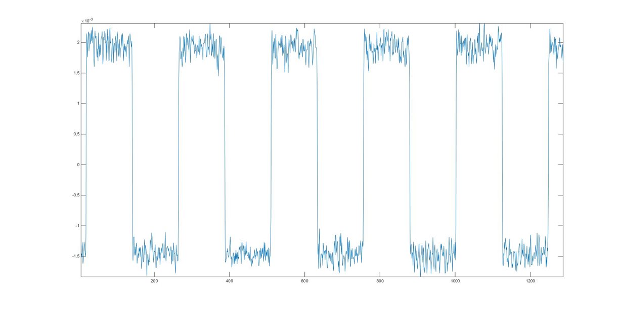
    You can see this noise is even present when measuring stuff like the Test signal generated internally. (Figure 3).

    I also selected components according to the datasheet's recommendations so maybe my PCB design is wrong in some way or a component is damaged. I will try soldering another prototype and test results but it would save me a lot of work if this one could be fixed.

    Thanks a lot for your time Brian,

    Pablo

  • Hey Pablo,

    Would you mind sending your schematic to pa_deltasigma_apps@ti.com?

    Brian
  • Hi Brian,

    I just sent you my design files to that email address. Let me know if you need them in some other format.
    I will solder the components for another prototype next week (same design) so I'll let you know if that works (just to check if any integrated component was damaged).

    Thanks a lot,
    Pablo
  • Hey Pablo,

    After quickly looking at your layout, there weren't any problems that immediately stuck out at me. I thought more about what you said before that even the internally generated test signal was noisy. That suggests that the noise is not coming from the inputs. The power supply rejection on this part tends to make me think that's not where the noise is coming from either. The only other thing that I can think of that could be causing the noise is the reference. From the schematic, it's clear you're using the internal reference. Is the internal reference buffer powered on? Are both C4 and C5 populated on your board?

    Regards,
    Brian Pisani
  • Hi Brian,

    Thanks for checking out the design. I was worried there might be some fatal design error I had overlooked. All the components are populated, including those capacitors. And the internal reference buffer is powered on too.

    I also think that the reference is probably be the culprit of the noise. Next week I will replace some components and re-solder connections just in case, and after that I will put together another prototype with the same design and test if the noise is also there. I'll let you know how everything goes next week.
    Thank you for your time and help :)

    Pablo
  • Hi Pablo

    I know it's an old post, but i have your problem with ads1299

    my board work good with ads1294 but with ads1299 i have gussain noise :|

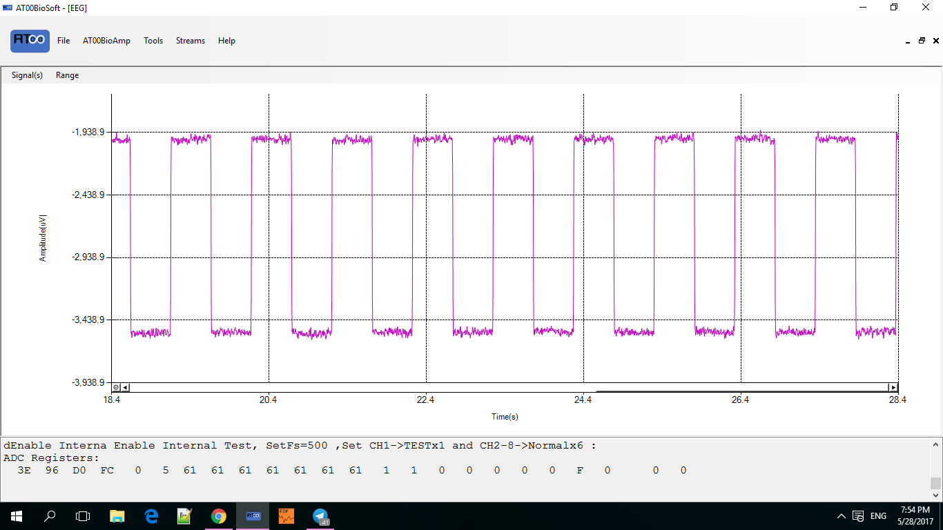
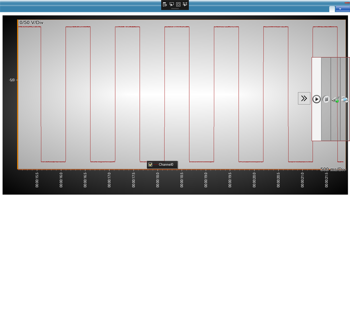
    this is my test signal screen shot, as you can see registers setting is ok and internal reference has been turned on.

    can you fix your problem?

    Thanksssss.

  • Hello Mohammad,

    The y-axis of your plot shows that the signal is always negative. Can you share the output codes corresponding to this data?

    Brian
  • Hi Brian Pisani,

    This is MCU code:

    for(j=0;j<3;j++)
    {
    while (SPI_I2S_GetFlagStatus(SPI2, SPI_I2S_FLAG_TXE) == RESET);
    SPI2->DR=0;
    while (SPI_I2S_GetFlagStatus(SPI2, SPI_I2S_FLAG_RXNE) == RESET);
    data_info[j]=(SPI2->DR);
    } 
    for(i=0;i<8;i++)
    {
    for(j=0;j<3;j++)
    {
    while (SPI_I2S_GetFlagStatus(SPI2, SPI_I2S_FLAG_TXE) == RESET);
    SPI2->DR=0;
    while (SPI_I2S_GetFlagStatus(SPI2, SPI_I2S_FLAG_RXNE) == RESET);
    data_info[j]=(SPI2->DR);
    
    }
    if(i<NumberOfChannels)
    {
    data[writerSeek++]=data_info[2];
    data[writerSeek++]=data_info[1];
    data[writerSeek++]=data_info[0];
    }
    }


    firstly, i read STAT and ignore it then read channel data and write it in a buffer and then convert MSB first  data to LSB first and send it to computer.
     

    this is computer code:

    	for (int j = 0; j < numberOfChannels; j++)
                            {
                                Int32 sampleData = 0;
                                for (int k = 0; k < 3; k++)
                                {
                                    sampleData += Convert.ToInt32(received[j * 3 + k] << (8 * k));
                                }
    							if ((sampleData & 0x1 << 23) > 0)
                                       sampleData |= -16777216;
                                    plotDataY[j].Add(Convert.ToDouble(sampleData)  * gainFactor);
    								/*
    									gainFactor=4.5/(2^23-1)*1000000/2=0.5364/2
    								*/
                                }
    						}
    

    Also AVSS=-2.5 , AVDD=2.5 and DVDD=3.3

    I think this problem pertain to IC or PCB.

  • This signal is recorded with ADS1294 with same PCB(approximately).

  • Hello Mohammad,

    I apologize I was not clear. I was looking for the hexadecimal codes of your output data so I could verify the alignment of the data on the y-axis of your display. Do you have this data?

    Brian