This thread has been locked.

If you have a related question, please click the "Ask a related question" button in the top right corner. The newly created question will be automatically linked to this question.

ADS1299 bias setting

Other Parts Discussed in Thread: ADS1299

Hi,

I am reading materials about ADS1299 and want to sample the EEG.

I read some materials on the OPENBCI website and compare it with the datasheet.

And the bias settings are different between them.

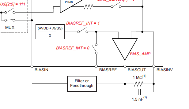
In TI's datasheet, it is shown below:

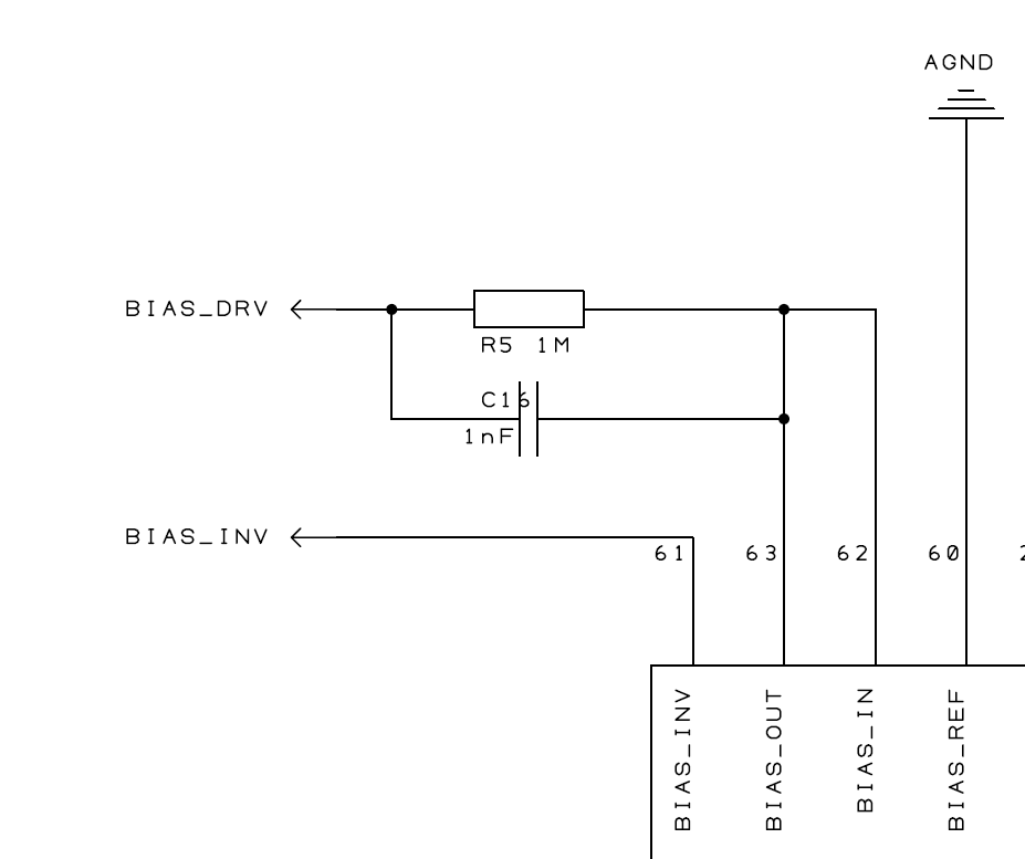
In the BCI, it is shown below:

Could you please tell me the differences between them and which is right/better?

Thanks,

-Di

  • Hey Di,

    Neither is really better. I did a little quick research and I found that the BIAS_INV pin connects to a header that seems to allow the daisy chain of multiple boards (very common for EEG applications). I'd imagine the intention was similar to that of the image on page 53 of the ADS1299 datasheet.

    The bias drive amplifier on the ADS1299 can be modeled like any other operational amplifier you've ever studied. It's purpose is to provide negative feedback from the inputs to the body in order to stabilize the body's common mode voltage so that it is within the measurable range for the ADC. In order for it to be effective, you have to connect the output to the inverting input through a feedback network (i.e. the 5 MOhm and 1.5 nF). If you wanted to daisy-chain devices, you'd also want to connect the BIAS_INV pins on all the devices that are daisy-chained so that the amplifier takes inputs from other devices in the chain as well as its own.

    In the datasheet, that connection is made in close proximity to the device for illustration purposes. On the Open BCI schematic, it seems they have left that to the user to do given that they provide flexibility on how many devices users can daisy-chain. Since you'd only want to power on one of the bias drive amplifiers out of all the devices that are daisy-chained, they do no close the loop for you on the board (I'm speculating on their design, but that seems reasonable).

    Regards,
    Brian Pisani
  • Brian,
    Thanks a lot!
    I am deeply moved by your kind help.
    I also read the datasheet carefully and I think the BIAS_DRV in the BCI SCH should connect to the BIASINV pin. I thing the BISAINV should NOT connect to AGND and how can this pin be used to stabilize the body's common mode voltage if so?
    For using only one device, I think the setting of bias should refer to the datasheet which connects the BIASOUT to the BIASINV using a feedback network.
    And if I use many devices to sample the EEG, should I just connect the BISAINV pins on all devices together? In this kind of situation should I power on one of the bias drive amplifiers or all(with the feedback networks I think the BISAINV pin should get an average bias value) and which is better/right?
    I am really interested in the ADS1299 but it is kind of difficult for me to use it.
    I am looking forward to your reply.
    Regards,
    -Di
  • Hey Di,

    No worries about the confusion! This is a complex device and it will take some time to understand fully how it operates.

    Were you referring to the BIAS_REF pin instead of the BIAS_INV pin? The BIAS_REF pin is connected to AGND on the Open BCI board. This is actually ok since the analog power supplies on this device are bipolar. Zero volts is actually right in the middle of the valid common mode range on that board. In addition, you don't need to use that voltage as the reference voltage for the bias amplifier since you can instead use an internally generated mid-supply voltage by setting bit 3 of the CONFIG3 register. In that case, the BIAS_REF pin will be internally disconnected from the amplifier.

    For using multiple devices, it's critical to understand how the amplifier operates. When using the BIAS_SENS functionality, the channel inputs you chose will be fed to the input of the amplifier. The bias amplifier is configured in a negative feedback scheme. In essence, the output of the amplifier is the amplified inverted input. The purpose of this is so when the input common mode drifts, the amplifier will drive it back to mid-supply. When using multiple devices, you only want to use one bias amplifier since you don't want multiple amplifiers battling over control of the body voltage. If you look at Figure 51 in the datasheet, you'll notice that only one of the amplifiers is powered on.

    You want your "master" amplifier to also produce feedback for the inputs to the daisy-chained devices in addition to its own. By setting the bits in the BIAS_SENSP/N registers corresponding to the inputs you want to feed into the amplifier on all the devices, the input to the amplifiers will appear at the BIAS_INV pin on all the devices. By connecting the BIAS_INV pins of the "slave" devices to the BIAS_INV pin of the "master" device, you are essentially adding those inputs for the master's bias amplifier to "sense". The output of the master device will be the amplified inverted input from ALL the devices.

    In an alternative scenario, it may not be necessary to use the BIAS_SENS functionality of the ADS1299. Instead, you may only wish to inject the mid-supply voltage on to the body without any active stability control. In that case, you still only want to use one of the bias amplifiers, but you can clear all the BIAS_SENS bits and there is no need to tie the BIAS_INV pins on all the devices together.

    Regards,
    Brian Pisani
  • Hi Brian,
    Thanks for your detailed reply and I will take a further reading about ADS1299.
    I will try my best tomake a EEG device.
    Best regards,
    Di