This thread has been locked.

If you have a related question, please click the "Ask a related question" button in the top right corner. The newly created question will be automatically linked to this question.

ADS131e08 and Input Protection Consideration

Other Parts Discussed in Thread: ADS130E08

Forking this post into it's own thread.. Here's the recap

Jon Mundall Wrote:

On another note we had issues with our ADS131e08's burning out when over saturating the inputs while running at a high gain, current was limited to 1/10'th of the data sheets recommendation but this appears to be invalid when using the PGA, please design accordingly or if anyone has ideas why this is happening please let me know.

The Ads131e08 is still by far the best part out there and were still using it on all our new stuff but it would be nice If it was a bit tougher or at least had documented behavior

Jon

In reply to Jon Mundall:

Hi Jon,

would you be willing to share with us (TI) under which conditions you experienced damage to the ADS130E08 (maybe in a separate post)? We would like to understand that in more detail.
As long as you limit the input currents to save levels there should no damage occur to the device. The PGA should have no influence here.

Regards,

Joachim Würker
Systems & Applications Manager
Precision Delta Sigma ADC's


@Joachim, 

This was our setup when we experienced the ic failure.

Power Supply is 2.4V Bipolar

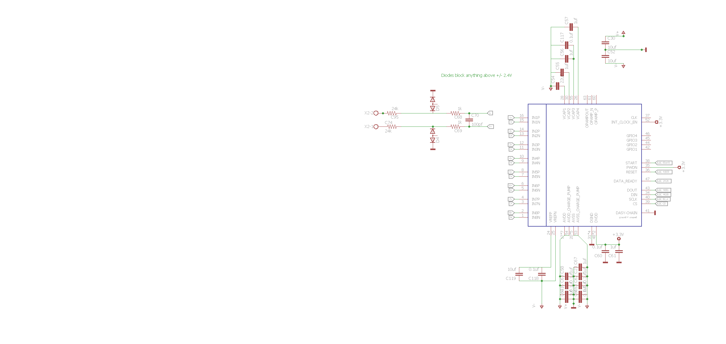
Chip failure occurred when a gain of 12 was used and 12V test supply was applied to both inputs terminals.. 12v through a 25K resistor should limit the current to 0.48ma, there was also diodes to protect in case of a surge as shown in the below schematic.

It is also worth noting that the entire chip failed and would no longer return it's ID via SPI

When testing the failure did not happen immediate although we did notice it was causing a drift in the other 7 channels consistently 

Further testing has not been performed beyond verification of digital voltage supply (3.3V) and analog supply (+/- 2.4V)

  • Hi Jon,

    thanks a lot for sharing this with us.
    If I understand correctly, the ADS130E08 did not fail to operate immediately after the overvoltage was applied?
    And when the device finally failed to operate, it failed permanently? Or did resetting or powering down and up again fix the problem?

    We might ask you to send the unit to us for failure analysis to understand what happened. But before doing that we might have some more question to you. I'll discuss with my team next week and let you know.

    Regards,
  • Hello Jon -
    Have you verified what the actual ADC input voltage is? Protecting the inputs with the resistance to limit the current is a good idea, but there is a voltage restriction on the inputs also that could cause damage. We notice the input diodes for protection but they also require a finite amount of time to protect and there could be a small time when the input voltage exceeds the specifications. This voltage repeated over time could cause failure or damage that could show up at a later time.
    An additional question, if you are putting a full scale voltage applied to the inputs, why do you need a gain? Full-scale of the ADC is +/-Vref/gain, so the largest signal you can resolve is +/-Vref (gain =1). The gain is really used for small signal to increase the dynamic range performance.
  • Thanks for getting back to me Greg,

    I have not verified the actual pin voltage before the chip died but did test after it had burnt and it didn't seem out of line... I can test again but don't like the idea of burning more devices... As far as the repetition factor, I don't think it played a role in our test case as it failed in 15m and the voltage applied was constant.

    I hear you about the gain, the gain doesn't appear to make sense however we use these as the front-end for multifunction analogue inputs (CTs, VT's 0-5V Sensors, DC Voltage etc) and the gain is used to match the full scale range of a wide array of sensors

    I'll test the pin voltage again, do you think it's important to keep a scope on it until the device fails?  It shouldn't change with a constant supply right?

    Jon

  • Hello Jon -
    Knowing the input voltage is an attempt to determine what is going on with the inputs. The concern is that the inputs are potentially seeing a out of range voltage and are being damage. Large voltages could not cause an instant fail, but instead damage the device so that at some point in the future it fails.
    While exploring possibilities, where does the supply voltages for the ADC come from? Values? Just trying to get the entire picture.
  • Hello Jon -
    In addition to helping you troubleshoot, we would like to have you return some of the damaged units for failure analysis through the distribution chain that you received them. This will allow us to confirm and get a better idea of where the problems may lie.