This thread has been locked.

If you have a related question, please click the "Ask a related question" button in the top right corner. The newly created question will be automatically linked to this question.

ADS1158 - Issues over long run test

Other Parts Discussed in Thread: ADS1158, AM3352, ISO7641FM

Hi all,

In one of our designs, we have used ADS1158 to measure the 8 analog inputs. 

We have configured ADC in Auto Scan mode with 8 channels enabled.

The set data rate is 1075 SPS , thus the sampling period is approximately equal to 0.93 ms. 

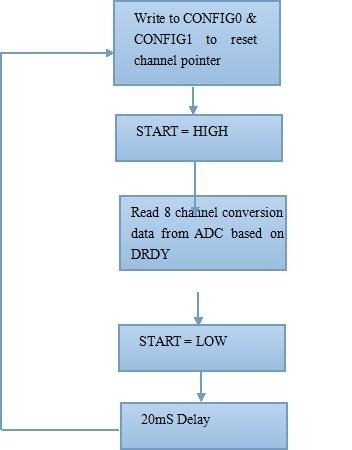
Below is the sequence of steps we are following for reading data from ADC: 

1) Write to CONFG0 & CONFIG1 registers to reset the channel pointer

2) Make 'START' signal HIGH 

3) Read 8 conversion data from ADC

4) Make 'START' signal LOW

5) Wait for 20mS

With the above configuration, we are facing some issues when tested for more than 24 hours.

We observed repetition in the channel data value of the ADC i.e any  two consecutive channels read value will be same. 

This error condition does not follow any pattern, basically it is random behavior.

From the ADC data sheet, we understands that Data out (DOUT) register of the ADC will be cleared after every read operation, and we don't find any possibility of reading the same data again for the next channel.

Can you please suggest any reasons for the above behavior over the long run test ?

Thanks,

Harsha

  • Harsha,


    I don't know of anything that would cause a duplicate read from one channel to the next. However there are a few different things to check.

    First check the software to make sure that they are triggering the data read after DRDY. I know in the flow diagram that they provided that it says that they do, but I would makes sure the /DRDY triggers some sort of interrupt that reads the data.

    Next, I'd make sure that this is really something that comes out of the device, and not some problem in handling the data. I would try to read the /CS, DOUT, DIN, SCLK lines with maybe a Protocol analyzer to make sure the data is coming out as a duplicate. Some logic analyzers can also handle triggers that will look for specific patterns.

    How often does this error occur? Is the rate of error constant or periodic?

    I would also have them set up the data read so that it also includes the Status Byte. This will include information about the channel ID and where the data came from. It's an option during the Auto-Scan mode that the customer could use for debugging this problem.


    Joseph Wu
  • Thanks for your response. 
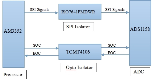
    In our design, ADC SPI is controlled by AM3352 processor. We have configured DMA, to read the data from the ADC. We are triggering DMA based on the DRDY signal. We have probed DRDY & SPI CLK pulses to make sure that the DMA is sending out  clock pulses only after the DRDY indication from ADC. ADC is sending out DRDY once in every 0.93mS & SPI CLK pulses are sent out within few uS of DRDY. 
    The data repetition period is random.  We had two separate setups for long run tests for around 10 days. We have observed this data repetition issue in 12 samples in one board & 4 samples in another board. Also, this behavior is not periodic.
    As per your suggestion, we will setup a board for testing with status byte enabled. Also, we will explore the option of connecting a protocol analyzer to read the actual conversion data from ADC.
    Meanwhile, we understand that the dataout register ( which will have the conversion result ), will be cleared after SPI read. Is this correct ? 
    If the dataout register is not cleared after SPI read , then our issue may be related to false DMA triggering, which may be resulting in reading dataout register twice for the same conversion. If the dataout register is cleared after SPI read, then even the false triggering will not result in duplicate data since first sample will be conversion result & second sample will be 0.
    Please confirm.
    Thanks,
    Harsha
  • Harsha,


    I've checked with the design group about what happens to with the dataout register after the first read. If you keep clocking SCLKs, it will continue to repeat clocking out the last data. In that case, the NEW bit in the STATUS register becomes very useful

    In addition to checking the NEW bit use the STATUS register can be used to check the channel. If you look at bits 4:0, the CHANNEL ID bits will show where the data came from. If there is a false DRDY trigger, at least you'll be able to check if the data is new, and where it came from.


    Joseph Wu
  • Thanks for the response.

    As per your suggestion, we have kept the board for testing with STATUS byte enabled.  With respect to this, we will update you further.

    Parallely, we have tried to read the ADC dout register after the first read by clocking the SCLKs with status byte enabled. We have done this by two different means. The conversion data of the ADC can be read by either Channel data read command or Channel data read direct. 

    In channel data read command, the data repetition was observed in the further read cycles after first read. Here, the new bit of STATUS byte was 0.

    In channel data read direct, the read data was equal to 0 in further read cycles after first read. Here also the new bit of STATUS byte  was 0. 

    Since, we have configured ADC in second mode, then we do not see a case when data can be repeated even if the channel is read again. The value should always be equal to 0 if channel is read repeatedly without a new conversion data.

    Thanks,

    Harsha

  • Harsha,


    At least for the second mode, you haven't seen a case of repeated data. I am a bit surprised that in read command and read direct you get repeated data for one but 0s out for the other. I may be able to find out if this was the intended behavior from the design group.

    As for reading the STATUS byte, remember that you can also get channel id information and you should be able to match the data to a particular channel.


    Joseph Wu
  • Thanks for the response.

    Below is the sequence and observation of analog input long run test :-

    1. As stated earlier, during our first iteration of long run test, we have kept  two boards without STATUS byte enabled for 10 days and observed the data duplication. The number of duplicate samples were 12 in first board and 4 in second board.
    2. Then, as per your suggestion, in second iteration we enabled STATUS byte in one board and started the test. We kept the board for 9 days and faced another issue instead of data duplication. We have set analog input to 8V and got 4 wrong samples with read data value less than 8V ( specifically, 2.3V, 7.23V, 7.92V and 0.88V). By reading the STATUS byte, we found that the NEW bit was set and the CHID [3:0] bits were corresponding to the correct channel. Thus, we think that the ADC conversion data has some issues.

    Also, below is the brief block diagram for your reference, explaining the design architecture :-

    We have couple of queries with respect to the possible reasons for this behaviour.

    a) As mentioned in block diagram, we have used SPI Isolator for the SPI signals in between ADC and processor. Is there any possibility of SPI isolator causing this issue ?

    (c) Below is the snapshot of the EOC signal for an entire conversion cycle of 8 channels. We have inverted the active level of EOC at output of opto isolator. This was done to accommodate the DMA triggering at rising edge.

    The snapshot details that as soon as EOC goes HIGH, processor is sending SPI clock pulses. Because of which EOC is going LOW immediately and the  observed HIGH voltage level is 2V (approx) instead of 3.3V.

    Is there any timing requirement for sending out SPI clock pulses after EOC transition ? Do we need to add some delay after EOC transition before sending out SPI clock pulses ?

    Please suggest.

    Thanks,

    Harsha

  • Harsha,


    If you are not using the STATUS byte, then the only way I can see of tracking this problem down would be to use a logic analyzer to and trigger off of a repeated pattern. I'm not sure I even have access to a logic analyzer that can do this. For this reason, I think it's best to check what happens using the STATUS byte.

    When using the STATUS byte, I think it's strange that you no longer see this problem, but instead get a different problem. With these wrong data, I'd still like to see the raw data coming from the ADC and not the converted data in Volts.

    For this problem, it looks similar to data that is interrupted by a DRDY event. I talk about this sort of thing in a blog post I wrote a few months ago:

    e2e.ti.com/.../help-i-can-t-talk-to-my-data-converter-what-s-wrong

    If you look through the blog, it's what I mention in reference to figure 3.

    As for your other questions, I've never used an ISO7641FM, so I don't know where it would have a problem. My guess is that this is not where you are having the problems. It is possible, but since you generally get the correct result, SPI isolator is the problem.

    My concern would be the opto-isolator, it looks as if the trigger for EOC is slow. The tail-off seems to last 100s of microseconds. What sort of loads are you using for the TCMT4106? I would use what they recommend and would hope that the transition times would be near the single microseconds. It's possible that this transition time is extended because of the bandwidth of the scope and that the transition is really much faster (and the EOC high is much higher than the 2V), but I'm not sure what scope and scope probes you are using.

    How are you generating the EOC? It is supposed to be indicated as /DRDY drops low. I'm not sure that's what I'm seeing on the scope. Also, in the plot, the first two EOC pulses are closer together than the remaining pulses. Is there a reason for that? I would have thought they would be equally spaced for the same data rate.

    The big concern is that the EOC sends the signal to the AM3352 is getting a delayed signal. If it is so delayed, the readout could be interrupted by another DRDY signal, which would corrupt the data.

    I'm not aware of any timing requirements for sending SPI clock pulses after the /DRDY besides the one shown in Figure 2. With the EOC looking like it could be delayed, I don't think that this could ever be a problem.


    Joseph Wu
  • Harsha,


    One other thing I forgot to mention deals with the AM3352. Is it possible that there is an interrupt that can give errors in communications? I really don't know the microprocessor side of things, so I don't think I could help debug problems when the processor is interrupted to work on other tasks.

    I just wanted to bring that up, just in case the interrupt was a possibility. Otherwise we could rule it out.


    Joseph Wu