This thread has been locked.

If you have a related question, please click the "Ask a related question" button in the top right corner. The newly created question will be automatically linked to this question.

ADS1294 can´t read register, no DRDY

Other Parts Discussed in Thread: LM3S8962, ADS1294

Hi I use the ADS1294 together with the Stellaris LM3S8962 Evaluation Kit.

After following the initialization process I don´t get a DRDY signal.

To test the communication I tried to read the ID register unfortunately  this is although not possible.

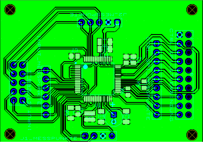
Here is my code and the Layout:

/*
 * EKG_V1.c
 *
 *  Created on: 15.04.2015
 *      Author: Alexander
 */

#include "EKG.h"

// INIT ----------------------------------------------------------------------------------------
void InitHW(void)
{
	SysCtlClockSet(SYSCTL_SYSDIV_1 | SYSCTL_USE_OSC | SYSCTL_OSC_MAIN |
		                   SYSCTL_XTAL_8MHZ);

	SysCtlPeripheralEnable(SYSCTL_PERIPH_GPIOA);
	GPIOPinTypeGPIOOutput(GPIO_PORTA_BASE,GPIO_PIN_7| GPIO_PIN_3 /*CS*/|GPIO_PIN_5/*SSITX*/);

	SysCtlPeripheralEnable(SYSCTL_PERIPH_GPIOC);
	GPIOPinTypeGPIOOutput(GPIO_PORTC_BASE,GPIO_PIN_7);

	SysCtlPeripheralEnable(SYSCTL_PERIPH_GPIOD);
	GPIOPinTypeGPIOOutput(GPIO_PORTD_BASE,GPIO_PIN_5);

	SysCtlPeripheralEnable(SYSCTL_PERIPH_GPIOF);
	GPIOPinTypeGPIOOutput(GPIO_PORTF_BASE,GPIO_PIN_0);

	// Ausgänge ausschalten
	// START = 0
	GPIOPinWrite(GPIO_PORTA_BASE, GPIO_PIN_7, 0x00);
	// Reset = 0
	GPIOPinWrite(GPIO_PORTC_BASE, GPIO_PIN_7, 0x00);
	SysCtlDelay(100);
	// PWDN = 0
	GPIOPinWrite(GPIO_PORTD_BASE, GPIO_PIN_5, 0x00);
	// CS = 0
	GPIOPinWrite(GPIO_PORTA_BASE, GPIO_PIN_3, 0x00);
	// SSITX = 0
	GPIOPinWrite(GPIO_PORTA_BASE, GPIO_PIN_5, 0x00);


	SysCtlPeripheralEnable(SYSCTL_PERIPH_GPIOG);
	GPIOPinTypeGPIOInput(GPIO_PORTG_BASE,GPIO_PIN_0);
	GPIOPadConfigSet(GPIO_PORTG_BASE, GPIO_PIN_0, GPIO_STRENGTH_2MA, GPIO_PIN_TYPE_STD_WPU);

}

void InitSSI(void)
{
	//
	// Enable the GPIO module that contains the GPIO pins to be used by
	// the SSI, as well as the SSI module.
	//
	SysCtlPeripheralEnable(SYSCTL_PERIPH_SSI0);
	SysCtlPeripheralEnable(SYSCTL_PERIPH_GPIOA);
	//
	// Configure the GPIO pins for use by the SSI module.
	//
	GPIOPinTypeSSI(GPIO_PORTA_BASE, (GPIO_PIN_2 | GPIO_PIN_3 |
				   GPIO_PIN_4 | GPIO_PIN_5));

	//GPIOPadConfigSet(GPIO_PORTA_BASE, GPIO_PIN_2 | GPIO_PIN_3| GPIO_PIN_4 | GPIO_PIN_5, GPIO_STRENGTH_8MA, GPIO_PIN_TYPE_STD_WPU);
	//

	SSIDisable(SSI0_BASE);
	// Initalize the hardware SSI module, using mode 1 and 8 data bits.
	//
	sysClk=SysCtlClockGet();
	SSIConfigSetExpClk(SSI0_BASE, sysClk, SSI_FRF_MOTO_MODE_1, //siehe S. 15
					   SSI_MODE_MASTER, 400000, 8);		// 10000 gleich 10KHz
	//
	// Enable the hardware SSI.
	//
	SSIEnable(SSI0_BASE);
}

void InitADS(void)
{
	// Power-up sequencing
	SysCtlDelay(1000);
	// Start = 1
	GPIOPinWrite(GPIO_PORTA_BASE, GPIO_PIN_7, GPIO_PIN_7);
	// PWDN =1
	GPIOPinWrite(GPIO_PORTD_BASE, GPIO_PIN_5, GPIO_PIN_5);
	// RESET =1
	GPIOPinWrite(GPIO_PORTC_BASE, GPIO_PIN_7, GPIO_PIN_7);
	// Wait for 0,275s
	SysCtlDelay(750000);		// bei 1 gleich 0,375 µS

	////////////////////////////////////////////////////////////////////////////////////
	// Test
		// Sende STANDBY
			//command_write(0x04);
			// Sende WAKEUP
				//command_write(0x02);
//////////////////////////////////////////////////////////////////////////////////////////////7


	// Sende SDATAC
	command_write(0x11);
	// Setze Config3 0xC0h
	reg_write(0x03, 0xC0);
	// Setze Config1 0x86h
	reg_write(0x01, 0x86);
	// Setze Config2 0x00h
	reg_write(0x02, 0x00);
	// Set ADS1294 CH to 0x01h
	reg_write(0x05, 0x01);
	reg_write(0x06, 0x01);
	reg_write(0x07, 0x01);
	reg_write(0x08, 0x01);

	// Start =1
	GPIOPinWrite(GPIO_PORTA_BASE, GPIO_PIN_7, GPIO_PIN_7);
	//sendSSI(0x08);
	//sende RDATAC
	command_write(0x10);
	//Sende SDATAC
	command_write(0x11);
	// Config2 auf 0x10h setzen
	reg_write(0x02, 0x10);
	// CH1SET auf 0x05h setzen
	reg_write(0x05, 0x05);
	// Sende RDATAC
	command_write(0x10);
	//command_write(0x11);

}

// MAIN ---------------------------------------------------------------------------------------
int main(void)
{
	//long receiveLength;

	InitHW();

	// Power-up sequencing
	SysCtlDelay(1000);

	SysCtlDelay(100);
	GPIOPinWrite(GPIO_PORTF_BASE, GPIO_PIN_0, 1);

	InitSSI();

	SysCtlDelay(5000000);
	GPIOPinWrite(GPIO_PORTF_BASE, GPIO_PIN_0, 0);
	SysCtlDelay(5000000);
	GPIOPinWrite(GPIO_PORTF_BASE, GPIO_PIN_0, 1);

	InitADS();

	SysCtlDelay(5000000);
	GPIOPinWrite(GPIO_PORTF_BASE, GPIO_PIN_0, 0);

	while(1)
	{	// TODO: Hauptprogramm

		// Sende WAKEUP
		command_write(0x02);
		SysCtlDelay(10);

		command_write(0x11);
		SysCtlDelay(10);

		command_write(0x12);
		SysCtlDelay(1000);

		// Sende STANDBY
		command_write(0x04);
		SysCtlDelay(10);


		reg_write(0x01, 0x86);
		test=reg_read(0x01);
		SysCtlDelay(10);
		command_write(0x12);

		SysCtlDelay(5000000);
		GPIOPinWrite(GPIO_PORTF_BASE, GPIO_PIN_0, 1);
		SysCtlDelay(5000000);
		GPIOPinWrite(GPIO_PORTF_BASE, GPIO_PIN_0, 0);
	}

}


// METHODES -----------------------------------------------------------------------------------
void sendSSI(unsigned long data)
{
	// CS Low
	//GPIOPinWrite(GPIO_PORTA_BASE, GPIO_PIN_3, 0x00);

	SSIDataPut(SSI0_BASE, data);

	// CS High
	//GPIOPinWrite(GPIO_PORTA_BASE, GPIO_PIN_3, GPIO_PIN_3);
}

int receiveSSI(unsigned long* data)
{
	int index=0;
	long receive=1;

	// CS Low
	// GPIOPinWrite(GPIO_PORTA_BASE, GPIO_PIN_3, 0x00);
	while (receive==1)
	{
		receive=SSIDataGetNonBlocking(SSI0_BASE, &data[index]);

		if (receive!=0)
		{
			index++;
		}

	}
	// CS High (optional)
	// GPIOPinWrite(GPIO_PORTA_BASE, GPIO_PIN_3, GPIO_PIN_3);
	return index;
}

void reg_write(unsigned long addr, unsigned long data)
{
	// CS Low (optional)
	//GPIOPinWrite(GPIO_PORTA_BASE, GPIO_PIN_3, 0x00);

	sendSSI(0x40|addr);
	sendSSI(0x00);
	sendSSI(data);
	SysCtlDelay(10);

	// CS High (optional)
	//GPIOPinWrite(GPIO_PORTA_BASE, GPIO_PIN_3, GPIO_PIN_3);
}

unsigned long reg_read(unsigned long addr)
{	int index=0;

	// CS Low (optional)
	// GPIOPinWrite(GPIO_PORTA_BASE, GPIO_PIN_3, 0x00);

	sendSSI(0x20|addr);
	sendSSI(0x00);	// 1 Byte

	while(index==0)
	{
	index=receiveSSI(&receiveData[0]);
	}

	SysCtlDelay(10);

	// CS High
	//GPIOPinWrite(GPIO_PORTA_BASE, GPIO_PIN_3, GPIO_PIN_3);

	return receiveData[0];

}

void command_write(unsigned long data)
{
	sendSSI(data);
	SysCtlDelay(10);
}

Layout:


I can also provide some Scope pictures:

green: CS,  red: DIN,  blue: SCLK, yellow: DOUT

I would be very thankfull for any help

regards Alexander

  • Hey Alexander,

    I noticed that your code pulls the START pin high during initialization which should cause the DRDY pin to toggle at the data rate. Have you probed the DRDY line with an oscilloscope to verify that it is not toggling? If you have, I'd advise checking the voltage at the START pin to verify that it is not being shorted somewhere accidentally.

    For your RREG command, there are not enough SCLK periods to shift out the data completely. From your scope shot, there appears to be two bytes: 0x21 then 0x00. The byte 0x21 will tell the device to RREG starting at register address 1 (the CONFIG1 register). the 0x00 will specify that you wish to read 1 register. After that, however, SCLK ceases to toggle so the data can never be shifted out. To read the register, you will need to extend SCLK periods by the number of bits you wish to shift out of the device. If I'm not mistaken, that can be done on the Stellaris by loading "dummy" data into the SPI data register. In addition, you'll need to issue the SDATAC command prior to reading registers. If the device is in RDATAC mode, it will not shift out register contents.

    Regards,
    Brian Pisani
  • Hello Brian thanks for your reply.

    I have already checked with an oscilloscope if the DRDY is toggeling unfortunately it does not.

    I have checked the Start pin as well but it stayes high during the initialization process. 


    Here is a new Picture where I have extended the SCLK like you desribed. I send now 2 dummy Bytes (0x00) in the read register function.

    Here I try to read the ID register. Yellow is DIN green is DOUT.

    additionally the code of my read register function:

    unsigned long reg_read(unsigned long addr)
    {	int index=0;
    
    	sendSSI(0x20|addr);
    	sendSSI(0x00);	// 1 Byte soll gelesen werden(n-1)
    	sendSSI(0x00);  //extend SCLK
    	sendSSI(0x00); //extend SCLK
    
    	while(index==0)
    	{
    	index=receiveSSI(&receiveData[0]);
    	}
    
    	SysCtlDelay(1000);
    	return receiveData[0];
    
    }

    Regards Alex

  • Alex,

    From what you said, it seems like the device should at least be toggling the DRDY pin. Perhaps there is an issue with the clock. How is the master clock being provided to the device? Have you pulled to CLKSEL pin high to use the internal oscillator or are you providing the clock externally?

    Regards,
    Brian Pisani
  • I have pulled the CLKSEL pin to high for using the internal oscillator. I measured the CLK pin with the oscilloscope with no result. Is it right that I should have a clock signal from the internal oscillator on this pin?

  • Hey Alex,

    Whether the internal oscillator is outputting data actually depends on the setting in the CONFIG1 register. The reset default is for the pin to be hi-z (a.k.a. no output). Without functioning communication, there is now way to change that. Can you probe the voltages at the following pins and let me know what they are: AVDD, AVSS, DVDD, VCAP1, VCAP2, VCAP3, VCAP4? Is the RESV1 pin tied to logic low?

    Regards,
    Brian Pisani
  • Hey Brian

    I measured the voltage of the pins and recognized that I have no voltage on the VCAP1. After Checking the Layout and improving the soldering  I get the 1.1V I also could get a first DRDY Signal with 250Hz.


    The peak of the DRDY signal is difficult to see in this picture because the cursor is hidding it.

    These are the other values:

    AVDD= 3.3V

    AVSS=0V

    DVDD=3.3V

    VCAP1=1.1V

    VCAP2=1.6V

    VCAP3=5.2V

    VCAP4=0V

    RESV1=0V

    Thank you for your support so far I will test the communication on the weekend again and let you know next week if things are going better.

    Regards Alex


  • Hey Brian

    I have the issue that I don´t get the 1.1V at VCAP1 anymore is there any possibility to fix this?

  • Hey Alex,

    I have an image of your layout, but would you also mind sending me your schematic?

    Brian
  • Hey Brian,

    here is my schematic.

  • Hey Alex,

    I'm having a tough time seeing it on this webpage for whatever reason. I will send you an email so you can send it to me that way.

    Regards,
    Brian Pisani
  • Hey Brian,

    I tested the communication between the ADS1294 and my Stellaris Controller but it dosen't work, the chip don't answer.
    I have attached my code for the communication. Is this code correct or have I something to fix?

    Is it possible, that you send me an example code for the communication?

    void InitSSI(void)
    {
    //
    // Enable the GPIO module that contains the GPIO pins to be used by
    // the SSI, as well as the SSI module.
    //
    SysCtlPeripheralEnable(SYSCTL_PERIPH_SSI0);
    //
    // Configure the GPIO pins for use by the SSI module.
    //
    GPIOPinTypeSSI(GPIO_PORTA_BASE, (GPIO_PIN_2 | GPIO_PIN_3 |
    GPIO_PIN_4 | GPIO_PIN_5));

    //GPIOPadConfigSet(GPIO_PORTA_BASE, GPIO_PIN_2 | GPIO_PIN_3| GPIO_PIN_4 | GPIO_PIN_5, GPIO_STRENGTH_8MA, GPIO_PIN_TYPE_STD_WPU);
    //

    SSIDisable(SSI0_BASE);
    // Initalize the hardware SSI module, using mode 1 and 8 data bits.
    //
    sysClk=SysCtlClockGet();
    SSIConfigSetExpClk(SSI0_BASE, sysClk, SSI_FRF_MOTO_MODE_1, //siehe S. 15
    SSI_MODE_MASTER, 1000000, 8); // 5Mhz...10000 gleich 10KHz
    //
    // Enable the hardware SSI.
    //
    SSIEnable(SSI0_BASE);
    }

    void InitADS(void)
    {
    // Aufrufen der PowerUp-Methode
    PowerUp ();

    // PDWN = 1 -->PDWN ist Low-Aktiv
    GPIOPinWrite(GPIO_PORTD_BASE, GPIO_PIN_5, GPIO_PIN_5);
    // Start = 1
    GPIOPinWrite(GPIO_PORTC_BASE, GPIO_PIN_5, GPIO_PIN_5);


    // DRDY should toggle at 250Hz


    ////////////////////////////////////////////////////////////////////////////////////
    // Test
    // Sende STANDBY
    //command_write(0x04);
    // Sende WAKEUP
    //command_write(0x02);
    //////////////////////////////////////////////////////////////////////////////////////////////7


    // Sende SDATAC
    command_write(0x11);
    //SSIDataPut(SSI0_BASE, 0x11);
    // Setze Config3 0xC0h
    reg_write(0x03, 0xC0);
    // Setze Config1 0x86h
    reg_write(0x01, 0x86);
    // Setze Config2 0x00h
    reg_write(0x02, 0x00);
    // Set ADS1294 CH to 0x01h
    reg_write(0x05, 0x01);
    reg_write(0x06, 0x01);
    reg_write(0x07, 0x01);
    reg_write(0x08, 0x01);

    // Start =1
    GPIOPinWrite(GPIO_PORTA_BASE, GPIO_PIN_7, GPIO_PIN_7);

    // DRDY should toggle at 500 HZ


    //send RDATAC
    command_write(0x10);
    //SSIDataPut(SSI0_BASE, 0x10);

    // Activate a 1mV Square-Wave Test Signal
    //send SDATAC
    command_write(0x11);
    //SSIDataPut(SSI0_BASE, 0x11);
    // write Config register 2
    reg_write(0x02, 0x10);
    // Set ADS1294 CH to 0x05h
    reg_write(0x05, 0x05);
    reg_write(0x06, 0x05);
    reg_write(0x07, 0x05);
    reg_write(0x08, 0x05);
    //send RDATAC
    command_write(0x10);
    //SSIDataPut(SSI0_BASE, 0x10);

    // Capture Data and Test Signal


    }

    // MAIN ---------------------------------------------------------------------------------------
    int main(void)
    {
    //long receiveLength;

    InitHW();
    InitDisplay();

    // Power-up sequencing
    SysCtlDelay(1000);

    SysCtlDelay(100);
    GPIOPinWrite(GPIO_PORTF_BASE, GPIO_PIN_0, 1);

    InitSSI();

    SysCtlDelay(5000000);
    GPIOPinWrite(GPIO_PORTF_BASE, GPIO_PIN_0, 0);
    SysCtlDelay(5000000);
    GPIOPinWrite(GPIO_PORTF_BASE, GPIO_PIN_0, 1);

    InitADS();

    SysCtlDelay(5000000);
    GPIOPinWrite(GPIO_PORTF_BASE, GPIO_PIN_0, 0);

    ////////////////////////////////////////////////////////////////////
    data_scan();

    // Soll später durch einen Interrupt aufgerufen werden
    print_display ();
    ////////////////////////////////////////////////////////////////////

    while(1)
    { // TODO: Hauptprogramm

    //SDATAC
    command_write(0x11);
    SSIDataPut(SSI0_BASE, 0x11);
    // Required afer SDATAC command 4 tCKL = 2µS
    SysCtlDelay(34);


    reg_write(0x01, 0x86);
    SysCtlDelay(10);

    test=reg_read(0x02);
    SysCtlDelay(10);

    // RDATA
    //command_write(0x12);

    SysCtlDelay(50000000);
    GPIOPinWrite(GPIO_PORTF_BASE, GPIO_PIN_0, 1);
    SysCtlDelay(50000000);
    GPIOPinWrite(GPIO_PORTF_BASE, GPIO_PIN_0, 0);


    }

    }


    // METHODES -----------------------------------------------------------------------------------
    void sendSSI(unsigned long data)
    {

    SSIDataPut(SSI0_BASE, data);

    }

    int receiveSSI(unsigned long* data)
    {
    int index=0;
    long receive=1;


    while (receive==1)
    {
    receive=SSIDataGetNonBlocking(SSI0_BASE, &data[index]);

    if (receive!=0)
    {
    index++;
    }

    }

    return index;
    }

    void reg_write(unsigned long addr, unsigned long data)
    {
    // CS Low
    GPIOPinWrite(GPIO_PORTC_BASE, GPIO_PIN_6, 0x00);
    // Wait 60nS Required min 6nS
    //SysCtlDelay(1);


    sendSSI(0x40|addr);
    sendSSI(0x00); //number of registers to be read/written -1
    sendSSI(data);
    SysCtlDelay(70);

    // CS High
    GPIOPinWrite(GPIO_PORTC_BASE, GPIO_PIN_6, GPIO_PIN_6);
    }

    unsigned long reg_read(unsigned long addr)
    { int index=0;

    // CS Low
    GPIOPinWrite(GPIO_PORTC_BASE, GPIO_PIN_6, 0x00);
    // Wait 60nS Required min 6nS
    //SysCtlDelay(1);

    sendSSI(0x20|addr);
    sendSSI(0x00); // 1 Byte

    // 2 Buffer-Bytes
    sendSSI(0x00); // 1 Byte
    sendSSI(0x00); // 1 Byte

    while(index==0)
    {
    index=receiveSSI(&receiveData[0]);
    }

    SysCtlDelay(1);

    // CS High
    GPIOPinWrite(GPIO_PORTC_BASE, GPIO_PIN_6, GPIO_PIN_6);

    return receiveData[0];

    }

    void command_write(unsigned long data)
    {
    // CS Low
    GPIOPinWrite(GPIO_PORTC_BASE, GPIO_PIN_6, 0x00);
    // Wait 60nS Required min 6nS
    //SysCtlDelay(1);

    sendSSI(data);
    SysCtlDelay(30);

    // CS High
    GPIOPinWrite(GPIO_PORTC_BASE, GPIO_PIN_6, GPIO_PIN_6);
    }


    Regards,
    Alex
  • Hey Alex,

    From your schematic, the RESET pin looks like it is being pulled low by a 10k resistor. I see that you pull it high in your code, but is it actually coming to a high voltage? Depending on your logic level, the 10k resistor will draw hundreds of microamps from whichever GPIO pin is controlling the RESET pin. Perhaps the Stellaris GPIO is having trouble sourcing it and the voltage droops down. Check the voltage at that pin.

    Regards,
    Brian Pisani
  • Hey I am now at the end of my Project.
    My status is now that I have communication between the µC and the ADS1294.
    I can write and read the registers and the ADS1294 reacts like it should do (for example I can provide the internal Oszillator on the refering pin) which is a great success for me considering all the trouble that I had. It is also possible to follow the initialization routine to the point that the DRDY signal is toggeling with 500Hz unfortunately I couldn capture the test Signal on the DOUT Pin. Nevertheless I rate this as an positiv result.

    I´m verry thankful for your support it helped me a lot.

    best regard Alex