This thread has been locked.

If you have a related question, please click the "Ask a related question" button in the top right corner. The newly created question will be automatically linked to this question.

ADS1247 – Far too long converted AD value settling time

Other Parts Discussed in Thread: ADS1247, ADS1248

Hello everybody


After going through datasheets and app notes again and again we would like to ask a question in this forum.


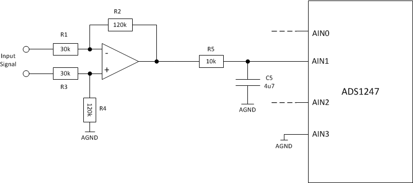
We are using an ADS1247 to measure 3 analog signals, thus we operate the ADC in single ended mode. The sampling rate is 5 SPS since we need high resolution. We are using the internal reference voltage of 2.048 V.


We also have an analog filter before the signal goes into the ADC to remove unwanted frequencies form the signal. It is also used as anti-aliasing filter.


In the schematic below just one channel (AIN1) is shown since the others are very similar.


Due to the filter's time constant of T = R5 * C5 = 10k * 4.7uF = 0.047 s = 47 milliseconds we expect the signal to stop drifting after 20 * T = 20 * 47 milliseconds = 940 milliseconds.


In order to check the step response we have made several experiments:


Experiment 1:

Apply a step and measure how long we can see signal drift in the converted AD values.


Result:

It takes about 6 seconds until the signal settles. W.r.t. the just calculated settling time above this is far too long.

When measuring the voltage over C5 then we exactly see the expected voltage curve!


Experiment 2:

Remove C5 to eliminate the low pass filter.

Apply a step and measure how long we can see signal drift in the converted AD values.


Result:

It takes about 2 seconds until the signal settles. This is more or less the expected behavior.


Questions:

  1. Why do we have such a significant difference in the settling time?

  2. When using an ADS1247 do we need to have an anti-aliasing filter before the ADC? Or is there already one included in the ADS1247 somewhere?

  3. We know that there are capacitors in the ADS1247, do we have to consider them when connection external capacitors? May they interfere?


Thanks for your support already in advance


Best Regards

Yves

  • Yves,


    Before we go to far, had a couple of questions.

    1. You use a gain of 4 difference amplifier on the input. Is there a reason you don't use the on-board PGA? I suspect you would get much better accuracy using the PGA.

    2. Do you have a bipolar supply? (Where AVDD=2.5V and AVSS=-2.5V). If you do that is fine, but if you are using a single supply (AVDD=5V and AVSS=GND) then the analog input tied to ground is outside the input range of the part. Since the input PGA is built like the front end of an instrumentation amplifier it still has a range limited to 100mV to either AVDD or AVSS.

    If the second is an issue, there might be settling issues because the PGA is outside the input range, I've never checked the settling time in an overload condition, but it might be a possibility.

    Continuing with your experiment, I'd like it if you could report your results with the data. Let me know what your input voltage is, what the reference is, and report the ADC code value. This will show the nature of the settling - if the settling is like an RC time constant, or which direction it's settling from, etc. Try to record data and the time interval.

    Is this a settling from start-up? If you have an external reference, it may be taking time for the reference to settle. Generally the internal reference will settle in several milliseconds at worst.

    What other parts of the blocks of the ADS1247 are you using? are you using the burnout current sources? The VBIAS? IDACs? I'd check to see that none of them are accidentally turned on.

    You already know that the last RC filter does make a large time constant to settle. I would go one step further and bypass the input amplifier just to make sure it's not coming from that. You should be able to put the source directly to the inputs (and you could even put the PGA in gain to make the data the same or similar).

    In answer to your questions so far:

    1. I'm not sure where the settling time is coming from. The ADC should be reading directly what the input is and there is no data point to data point latency. I've never seen long settling times for this device, unless it is a problem with the reference or the input.

    2. For the anti-aliasing filter, there isn't one built into the device. However, I generally have gotten good results with moderate filtering. If you want an example, I'd look at the ADS1248EVM. Find the users guide and look at the schematic.

    3. The internal capacitors are used to sample the input signal. These values are in the several pF range. Often the differential capacitance used for the filtering (between AINP and AINN of the ADC) can be used as a ballast to source charge for each sample of the ADC. They typically do not interfere and usually help with the sampling process.


    Joseph Wu
  • Hi Joseph


    First of all, thanks for your answer.

    To completely investigate all your valuable inputs we would need some time.


    Regarding your questions I can already say the following:


    1. I agree, but when I joined the project the hardware design was already made. So this is a point which we can do better in upcoming projects.


    2. Our supply is (AVDD=5V and AVSS=AGND). But… according to the datasheet the following conditions must be met: AVSS – 100mV < AIN3 < AVDD + 100mV. And this seems OK for AIN3 which is tied to AGND. Or do I miss something here?

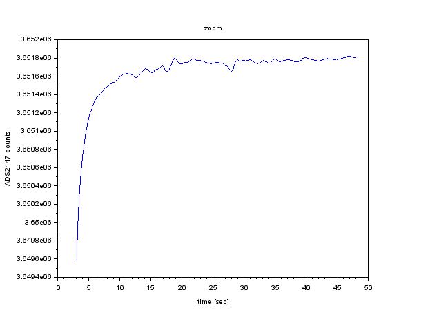
      I tried to record some data and prepared a plot where you can see that the 'slow settling' is some kind of a RC behavior.

      When looking at the overview plot then we see a nice settling, when zooming in and starting from seconds 3 we see the ADC counts climbing up slowly. And this causes our 'headace'.


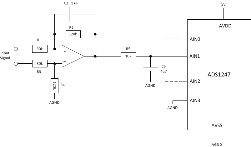
      This data was captured from an experiment with an additional C2 with 1uF in the feedback path of the OPAMP (I've updated the schematic). So the dominant time constant is 120k*1uF = 0.12 seconds, which is also quite small. After 20 time constants (2.4 secs) we should have reached 99.9999998 % of the end value. We can see exactly that time constant when measuring the voltage over C5.

      The voltage starts at 0V and goes up to about 890 mV.


      We think this behavior is not a start-up thing, we can see it every time the input signal makes a step.

      All other functional blocks of the ADC (e.g. VBIAS, IDAC) are turned off.

      Regarding my own question No. 2:

      According to the nyqusit theorem we should add a low-pass of 2.5 Hz when sampling at 5 Hz. Otherwise we can get aliasing. Correct? The values on the EVM are quite small (47 ohms, 47 pF) and seem to be there for EMI protection only.


      We will keep you updated.


      Best regards from sunny Switzerland

      Yves

  • Yves,


    My first thought about the long recovery is that this may be caused by the input being outside of the input common mode range. Since the PGA (used even when the PGA is set to 1) is built like the front end of an instrumentation amplifier, the overload may be causing a long time recovery. This may be compounded by the fact that the PGA is chopped to reduce offset.

    There is one test you can try, but it does require some re-wiring. I would attach the reference end of the difference amplifier (from R4) to VREFOUT instead of AGND. Then attach A3 to VREFOUT as well. Then the input signal would be measuring the input signal offset by the voltage on VREFOUT. If you are having problems with the overload and recovery of the PGA, then this should solve the problem.

    Give this a test. If it doesn't help, I may need a more detailed schematic.

    For the second question, I'll point out that the ADS1248 is a delta-sigma (or oversampling converter). This means that the input is sampled at the modulator rate, not at the data rate. With a data rate of 5 SPS, the modulator frequency is 32kHz (based on Table 8 of the datasheet). In that case if you want to hit the Nyquist frequency it goes to 16kHz.

    I usually recommend the filtering that's shown on the EVM. Generally, I use modest filtering unless I know that I can expect in-band noise.

    If the filters are too low in bandwidth, then it may interfere with the sampling of the input. Remember that the input is a charged capacitor sampling that samples a the modulator rate. In that case you want to be able to make sure the sampling capacitor settles at each sample. If it doesn't, then it may appear as a gain error.


    Regards, from sunny Tucson, Arizona (although we've had thunderstorms lately)

    Joseph Wu
  • Hi Joseph

    Since I'm more a firmware than a hardware engineer I had to check literature to read how delta-sigma converters work. After polishing up my delta-sigma knowledge and reading your answer again it suddenly was clear to me that we designed the low pass filters for a classical ADC instead of a delta-sigma ADC.

    My understanding now is that due to the very high sampling frequency of 32 kHz the filter requirements are significantly lower compared to classical filters. And since our desired signal frequency never gets that high we anyway never get into trouble.

    What we implement now is that we filter the desired signal with a low passes that have a dominant corner frequency below 16 kHz to get rid of potential aliasing. As a second stage we have the ADS1247 built in FIR filter that has a corner frequency of 2.26 Hz at the configured 5 samples per second.

    First measurements showed that this helps to avoid long settling times :-)

    Just to be 120% sure: I assume that this is the right way to use a delta-sigma converter, correct?

    Regards
    Yves
  • Yves,


    Yes, that is correct.

    There are two things that I'd like to mention again. First is that if you are using a +5V supply, and the negative input is tied to GND, it is outside the common-mode input range of the part. If you've made the adjustment that I mentioned by tying the input to the VREFOUT, you should be ok. Second, I've had good performance using the filtering on the ADS1248EVM. I generally don't like to over-design the input filtering. However, if you are getting good results with what you have, that's what is important.

    Good luck with your project. If you have any other questions feel free to post back to the forum.


    Joseph Wu
  • Dear Joseph
    I'm just writing to say: Thank you very much for your support. it really helped to understand the true nature of delta-sigma converters.

    Best regards
    Yves
  • Yves,


    I'm glad I could help. If you have any more questions about this device or other data converters. Please feel free to post back again.


    Joseph Wu