This thread has been locked.

If you have a related question, please click the "Ask a related question" button in the top right corner. The newly created question will be automatically linked to this question.

AMC7812 SPI communication

Other Parts Discussed in Thread: AMC7812

Hello TI Team,

I am using a controller that cannot send all 24 bits together over SPI but 8 bits 3 times. Does AMC7812 support it?

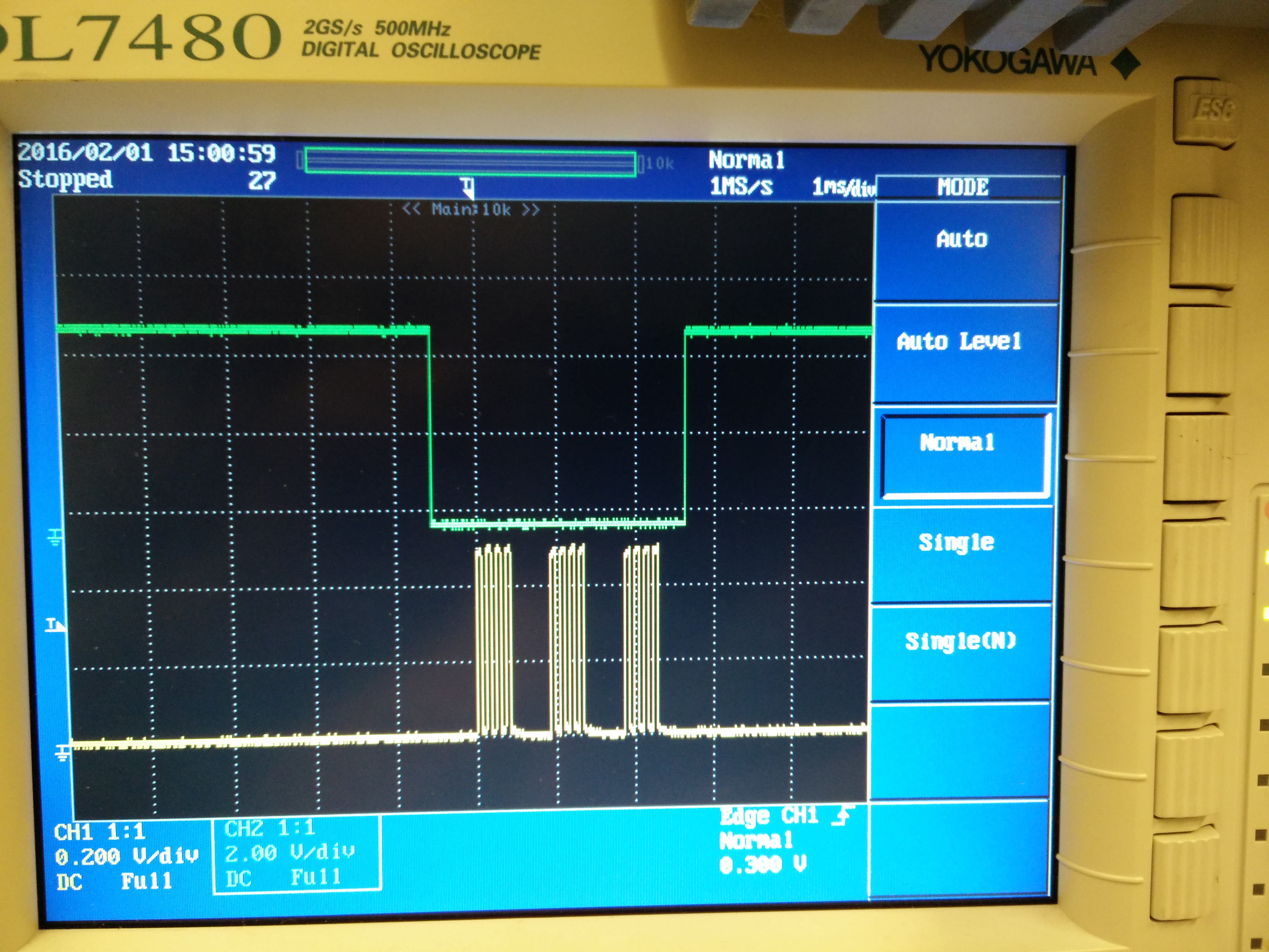
Attached a screenshot of DSO.

I am trying like this for quite long time now but get random data from AMC7812.

Thanks

 Regards,

Vitthal

  • Howdy VItthalk,


    The device should work as specified as long as the above meets the timing requirements specified in the AMC7812 datasheet.  The above image does not include any timing metrics, can you recapture with the below requests?


    - Include time division and other signals in one oscilloscope capture (SCLK, SDI, CS)
    -Second (magnified) oscilloscope capture of SDI signal in relation to SCLK

    It should be possible to communicate as you illustrated (8 bit packets).  In fact, the AMC7812EVM includes a USB microcontroller interface that communicates by bit-banging 8 bit packets, which includes small gaps between each packet.


    Best Regards,
    Matt

  • Hello Matt,

    Thanks for quick reply.

    Attached few more captures of oscilloscope. I had just 2 channel scope so could not capture everything together but tried to capture V/div and Time/div in all captures.

    Image1:

    1) Green: CS

    2) Yellow: SDI (0xaa,0xaa,0xaa)

    3) Time division: 1ms/S

    Image2:

    1) Green: Clk

    2) Yellow: SDI (0xaa,0xaa,0xaa)

    3) Time division: 500 us/S

    Image3(Magnified):

    1) Green: Clk

    2) Yellow: SDI (0xaa,0xaa,0xaa)

    3) Time division: 20 us/S

    Thanks

  • I noticed that the typical gap between the 8-bit packets is roughly 500 us, I'll ping our designers to see if this length is still acceptable for valid communication.  In the meantime, can you provide the state of the I2C/SPI pin of the device?  Is this pin pulled high?

    0xaa indicates a register read of 0x02, therefore the data will more than likely be changing based on D2 Temperature Data.  It may be best to read a static variable for correct SPI communication.  Please read from register 0x6C.  Therefore the first 8 bits of the read should be 0xEC.  You should read 0x1220.

    Also, please verify that two read frames are issued for correct read.  This is explained in the image below, which is found on page 56 of the datasheet.

    Please read from register 0x6C and capture SDI/SCLK/SDO, this will be a good step in our debug of this issue.  You can probably perform the captures in 2 difference images.  One with (SCLK/SDI) and the other in (SCLK/SDO).

    Best Regards,

    Matt

  • Matt,

    Now gap between 8 bit packets is 'one clock cycle only'. Yes, SPI/I2C pin is pulled high.

    Attached few more captures as you requested and managed to capture CLK, SDI and SDO together.

    First channel: Clk

    Second channel:SDI

    Third channel: SDO

    1) Sending 0xEC to read 0x6C register but SDO data is 0.


    2)  Sending 0xCD to read 0x4D register but SDO data is random.


  • Ti Team or Matt,

    Can you please provide more details on this issue.

    Thanks
  • Vitthalk,

    Can you provide a schematic so we can verify the connections and supplies? Alternatively, if you wish the schematic to remain private I can send you my email via e2e messages.  

    From what I gather from the images, the SCLK frequency seems to be around 4KHz -- I will email our designers to find out if this frequency is acceptable.  I'm not currently in office, but I plan to recreate your setup with communication speed so we can debug and find a solution.

    Best Regards,

    Matt