This thread has been locked.

If you have a related question, please click the "Ask a related question" button in the top right corner. The newly created question will be automatically linked to this question.

ADS1299EEGFE-PDK Single Ended Analog Input Problem

Other Parts Discussed in Thread: ADS1299

Good Afternoon,

I am attempting to input a sinusoidal signal to the ADS1299 EVM using J6 similar to the signal that can be seen in section 8.6 (page 49) of the user guide, I am aware that all 8 channels can be used simultaneously but for starters I would simply like to use channel 1 alone. 

I followed the instructions found in section 4.6.2 (page 17) for single ended inputs however the wave I am getting is completely wrong as my input is sinusoidal (snapshot of output is attached). I followed the instructions exactly even with the default jumper settings, which led me to believe there might be a typo because one of the settings requires that JP18 be set to 2-3 rather than 1-2 the way it came and whenever I did this the analysis would run indefinitely until I manually closed the GUI, I looked at the schematics and JP18 relates to the clock and by setting 2-3 the configuration is set to EXT_CLK, please confirm if this is a typo. I also made sure to close the SRB1 pin in the GUI and in channel registers I set TEST Source to Driven Externally, under Globally Set Channels I set channel 1 to Power, SRB2 Open and Channel Input to Normal Electrode (attached is a snapshot of the settings. 

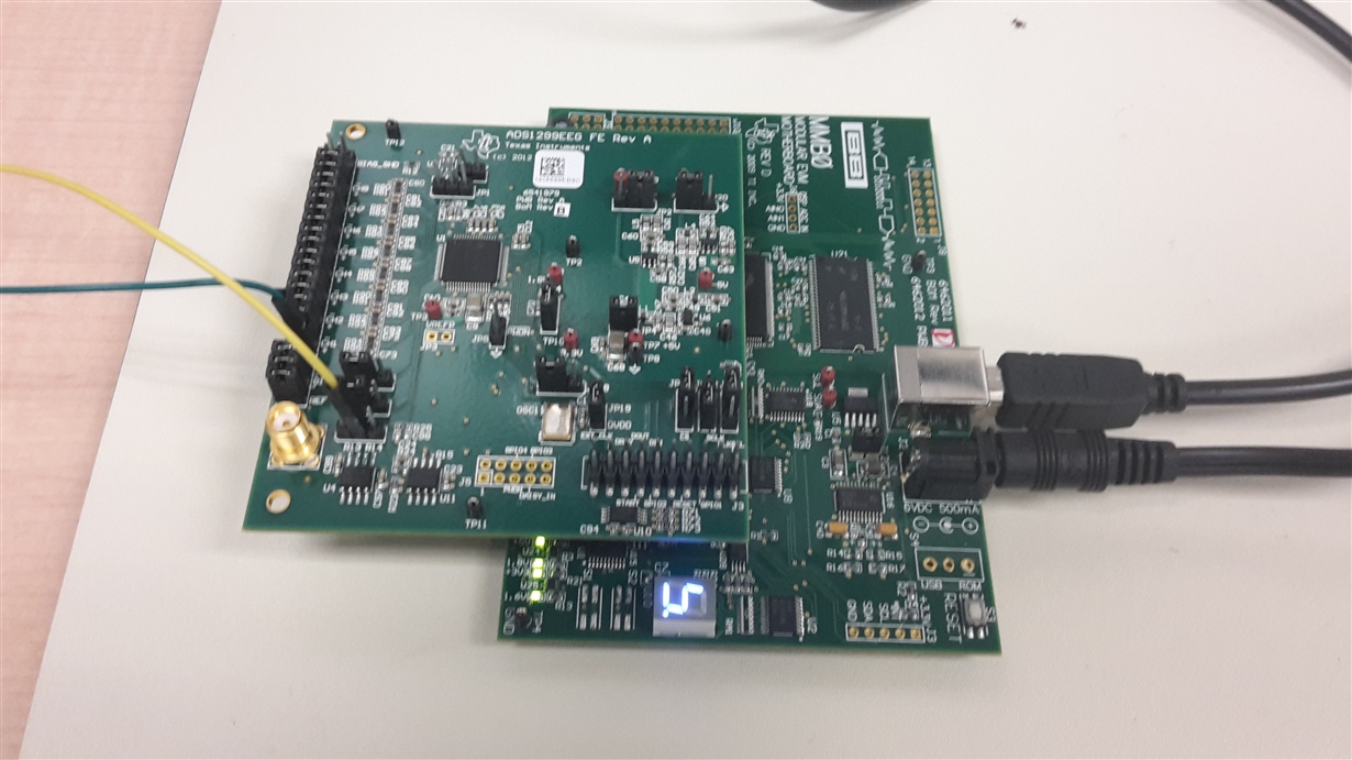
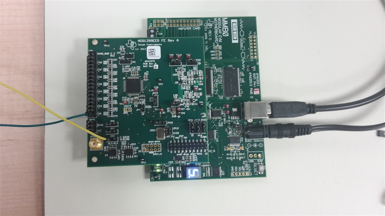
Attached are also pictures of the set up on the ADS1299, I have pin 36 of J6 connected to my input and pin 2 of JP8 (which I believe to be the pin for SRB1) connected to ground. 

Thank you for your help,

Carolina

  • Hi Carolina,

    I've moved this post from the Medical Forum to the Precision Data Converter Forum, where the ADS1299 is supported. I'm sure you'll find an answer here.
  • Hello Carolina,

    I believe that is actually the correct readout of the signal you supplied. If you notice, the sample rate you have set is equal to 250 SPS. You are providing a 100 Hz signal which means there will be only 2.5 output samples per input period. This is not very well oversampled and thus you do not get a good representation of the input signal in the digital domain.

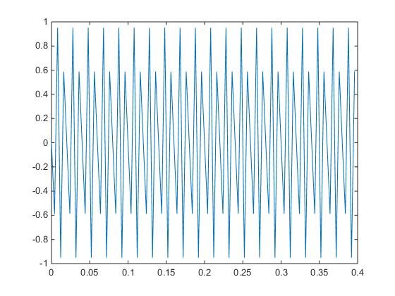
    Just to check my theory, I typed the following commands into MATLAB. They generate a 100 Hz sine wave that is sampled at 250 Hz (I added a 90 degree phase shift to make it so the signal and sampling were a little out of phase).

    t = (0:99)/250;
    x = cos(2*pi*100*t+pi/2);
    plot(t,x)

    The result of this code is shown here:

    Note how when the sine wave is not sampled fast enough, it seems distorted. My recommendation would be to either decrease the signal frequency or increase the sample frequency and see if you can get good results that way.

    I have confirmed that J18 pins 2-3 should be shorted to provide the oscillator output to the CLK pin.

    Regards,

    Brian Pisani