This thread has been locked.

If you have a related question, please click the "Ask a related question" button in the top right corner. The newly created question will be automatically linked to this question.

Questions about ADS1292 (2 Electrodes use, # of Channels, RLD)

Other Parts Discussed in Thread: ADS1291, ADS1292, ADS1292ECG-FE, ADS1292R

Hello,


I am making a design of a small portable 1 Lead, i.e. 2 Electrodes, ECG with NO RLD. This device will be used for animals. I was thinking about using one of the TI’s IC chips for ECG, in particular ADS1292 or ADS1291, hence the following questions:


- First of all, ADS1291 is stated as a 1 channel chip, does it mean I can only connect 1 electrode and RLD or how does one channel work? If I can only connect one Electrode it’s not an ECG anymore.


- In datasheet, it says ADS1292 is a two channel chip (in the table), but on your web page(www.ti.com/.../description) it says: “# Input Channels: 3”, so which is it?


- Is it possible to achieve good signal/noise performance using a ADS1292 chip without RLD? The documentation of the similar chip from Analog Devices advises to use 2 resistors to connect the RLD in a loop to electrodes to bias these electrodes to the center of the internal ADC input range. Therefore, improving the overall performance even without physically(connecting to the patient) using RLD. Is there such an option in this chip? How can I improve the performance without the use of RLD?

Kind Regards,

Den

  • Hi Denis,

    The ADS1292 has two ADC's internally while the ADS1291 only has one. There are also auxilliary channels, but they are not used for ECG purposes. The datasheet should be your main focus rather than the parametric table, we'll get that 3 channel inference cleared up.

    If you take a look at the block diagram of the ADS1292 (Figure 18, page 16) you'll notice that the RLD amplifier can be connected to a mid supply source and you could bias the electrodes in a similar fashion as you mentioned above. You don't necessarily have to use the RLD feature to achieve good performance. A good starting point for your design might be with the ADS1292ECG-FE evaluation module - there is a schematic of the ECG related functions on page 51 of the Users Guide.
  • Hi Tom,

    firstly, thank you for your reply. Secondly, I've bought the ADS1292ECG board, however I couldn't make it work on Windows 10. Basically, when I connect the board through the USB to the PC, the device manager assigns it to a “USB Serial Device (COMx)” under "Ports (COM & LPT)". When I try to update the driver manually Windows says that “The best driver software for your device is already installed”. I’ve tried the trick with turning off the driver signature enforcement. Still didn’t work. Whatever I do, I can’t make Win 10 recognize the board. Is it a known issue and the board just doesn’t work under Windows 10?

    Kind Regards,
    Denys
  • Hi Denys,

    Do you have a Win7 machine that you can install the software on?  There have been some mixed success stories here on the Precision Data Converter Forum with folks being able to get the software to work on Win10.

  • Hi Tom,

    regretfully, no. Well, if there are some success stories - there is a chance I will be able to succeed too.

    Kind Regards,
    Den
  • Hi Den,

    Check out this post:

    e2e.ti.com/.../1610010
  • Hi Tom,

    Yeah, I've read it before. You know, "read the forum before posting your question" - I try to follow that rule :)
    Though, I did solve the problem, my answer will probably be useless to others, nonetheless:

    I have around 8 USB ports, I didn't test them all in the beginning, just those which I use mostly. Now I've tested them all, and strangely enough on the USB 3.0 port it worked... figures. Of course, I had to disable "Driver Signature Enforcement" first.

    Now I will start with the board testing. I won't close this thread yet, since I might have some questions regarding ADS1292.

    thanks for your help and kind regards,
    Den
  • Here are the footprints you asked for...

    ADS1292_PCBFP.zip

  • Hi Tom,

    thanks for the footprints!

    After playing with the ADS1292 Device Kit for the past few days, I have the following questions:

    1) Does ELA channel work as a real Left Leg Electrode? In the schematics, it’s just connected directly to the Left Arm Electrode channel in series with a 51K resistor. Could you please explain to me the idea behind this connection?

    2) I have tested ADS1292 with and without RLD with Ag/AgCl Electrodes and it gives really good results. In fact, there is not much difference in performance if I don’t use RLD somehow. The problem is that I don’t use Ag/AgCl Electrodes in my design. I have to use EPIC sensors from Plessey semiconductors, yes EPIC is the name… here is the datasheet of what I am trying to connect to the ADS1292 Device Kit – http://www.plesseysemiconductors.com/doc/?id=291501.

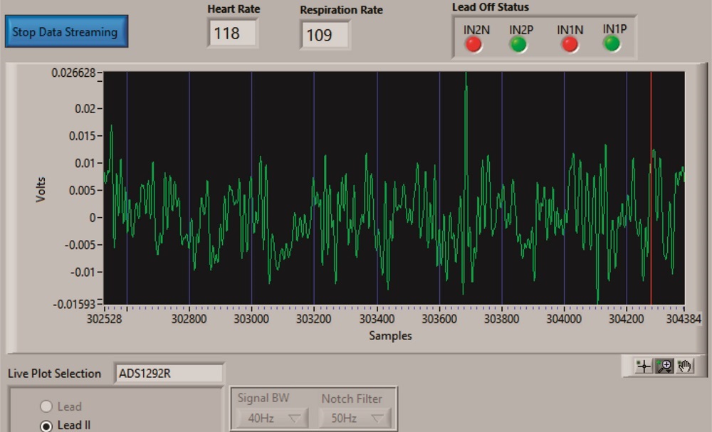
    These are capacitive sensors and should deliver really good performance even if measured through a T-Shirt. In fact, when I am using Plesseys’ evaluation board, the results are really good even through a T-Shirt. However, if I connect these sensors to the ADS1292 Device Kit, the results are terrible. In fact, I can only see noise. Here is a screen shot:

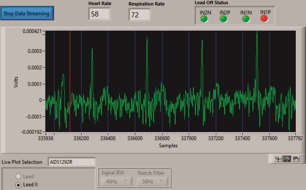
    I have also tested these Plessey sensors with similar chip from Analog Devices ADAS1000 and it worked pretty well. So, I am assuming that it also should work with the TI chip. Also, when I set Channel Input to: “Input Short” the results do become better:

    Of course not enough to be considered an ECG. 

    Also, while using the sensors from Plessey the Lead of Status turns on and off all the time on all channels, i.e. it shows that there is no constant contact although the electrodes are attached to my body very tightly. 

    My questions are:

    -          Can ADS1292 work with this kind of capacitive sensors, i.e. such as Plessey EPIC Electrodes (www.plesseysemiconductors.com/.../

    -          Why does it work with Short Input Settings better? (even if it’s still bad)

    -          Could you suggest me some directions on what should I set up in the registers to get max performance for my type of electrodes/sensors?

    Kind Regards,

    Den

  • Hi Den,

    Unfortunately we've not used that particular sensor here in our lab. I suspect the issue might be to biasing though, when you used the other ECG chip, was that on an evaluation board like our ADS1292 or was it your own wiring/hardware? One thing about the input short test is that the inputs are shorted internally to the ADS1292 - it does not have the means to actually 'short' your leads together, so nothing on the outside of the chip comes into play. Send along your register settings and a schematic for the EPIC electrodes if you happen to have one.

  • Hi Tom,

    Unfortunately, I don’t have schematics and the manufacturer will not disclose them to me.

    I am thinking that the problem is with biasing as well. The sensors I am using are a type of “active electrodes”, i.e. they have an op. amp. right next to the sensors’ output. Therefore, they are biased with +/-2.5 Vdd/Vss. The output of the sensor can cover a range from +2.1V to -2.1V.

    As I understand, the ADS1292 dev. kit has differential input configuration, which is described in sbas502b.pdf page 20, i.e. each INP and INN inputs can swing from CM + Vref/2 to CM - Vref/2, where CM is equal to (INP + INN)/2.  To allow for such a large swing from EPIC sensors I’ve set Ref. Voltage to 4V and PGA to 1. The result was the same as when I shorted the input, i.e. I could see something resembling an ECG signal, yet it was still too noisy. (Note, with 2.4V reference voltage I could see only noise).

    Regarding the ECG chip from Analog Devices: yes, I also used a Dev. Kit -www.analog.com/.../UG-426.pdf. I also don’t understand why the chip from Analog Devices shows better results while it’s input range is smaller, i.e 1.3 V.


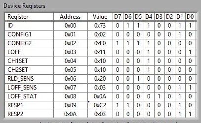
    Here are my register settings:

    I know I’m asking a lot of questions, but if you could answer them for me, it will greatly help me in the understanding of ADS1292, therefore:

    Questions to the register settings:

    • Since I am using capacitive sensors, I am assuming that AC Lead-off detection is more suitable than DC Lead-off detection?
    • Does Lead-off detection influence an ECG signal quality?
    • How do you decide on the PGA chop frequency? I just went with the lowest frequency, i.e. fMOD / 16.
    • Could you please give me advice on the right register settings for respiration measurement on channel 1? Somehow even with normal electrodes, i.e. Ag/AgCl, my respiration measurement is incorrect. Jumping from 30 to 70 and rarely to 19-20, which is close to the truth.
    • Could you advise me on the right settings for the RLD in RLDSENS register? Should I have it turned on for both channels or only for channel 2, where I am measuring an ECG signal? Should both positive and negative inputs be on or only one of them?
    • Since each Left and Right Electrode go to channel 1 and channel 2(page 51, slau384a.pdf), I am assuming that LOFF1N + LOFF1P set to 1, should be enough to detect if the electrodes are properly connected? 
    • Why does respiration detection make the signal a lot noisier? (tested with Ag/AgCL Electrodes, with EPIC electrodes the signal is too bad)
    • Which Respiration control frequency should I choose and why?

      Questions to the Dev. Kit Board Schematics:

    • The way channel 1 is terminated in ADS1292R Dev Kit, page 51 of slau384a.pdf, I am assuming that I can only measure Respiration on it?

     Kind Regards,

    Den

  • Hi Den (and Sascha),

    Sorry for the delay in getting back to you. There are a couple of application notes (one on AC vs DC lead off detection and another on respiration) that you might find useful. They are located here:

    www.ti.com/.../technicaldocuments

    I'm looking into getting some of the Plessey EPIC electrodes to see if I can come up with register settings that make your setup work better.
  • Hey Tom,
    did you manage to try the EPIC electrodes eventually? I have pretty much the same problem as Denis, and furthermore I didn't really understand if it's possible to implement the RLD with such electrodes. Do you have any clue about it? If it's possible to use it, can you please give me some tips about the right configuration of the registers in this case? I also use only 2 electrodes with the ADS1292R, and they are connected to the first channel, do you think this could influence the output, since channel 1 is primarily for respiration?

    Thank you in advance
    Regards,
    Stella
  • Hi Stella,

    I did get some of the active electrodes, but I was not able to implement RLD with them.  Channel 1 can be used for ECG or respiration, so that should not be a problem.

  • Hi Tom,

    thank you so much for the quick reply. At this point I would like to ask you if you where anyway able to obtain a clean signal, or in your opinion it's not really possible to obtain a good quality signal with this kind of electrodes interfacing the ADS1292R. 

    Thank you for your help.

    Regards

    Stella

  • Hi Stella,

    Yes, you can get decent signals from the electrodes.  I found the package to be a little difficult to prototype with, but otherwise they are easy to use.

  • Hi Tom,
    is it possible for you to share with us the registers configuration you used? Cause I don't understand why my signal is that noisy.
    I personally set the registers as follows:

    CONFIG1: 00000011
    CONFIG2: 10100001
    LOFF: 11110000
    LOFF_STAT: 00000000
    CH1SET: 00010000
    CH2SET: 10010001
    RLD_SENS: 11000000
    RESP1: 00000010
    RESP2: 10000111

    My fclk = 512 kHz and sampling_freq = 1000 SPS
    After writing the registers I'm able to properly read them back, and I issue the Offset Calibration Command, followed by a delay of 200ms. As I said my LA and RA electrodes are connected to the Channel1. I disabled the Lead Off Detection, cause I think is useless with this kind of electrodes, am I right?.
    I made different configuration trials, and there's a strange phenomenon I don't understand. If I maintain the same configuration for CH1SET and CH2SET, but I torn on the RLD circuit on every channel through the RLD_SENS register, my signal is slightly better, even if I don't actually drive it to the input channels, how is this possible?.
    Thank you in advance for your help.
    Best Regards
    Stella
  • Hi Stella,

    I don't remember off the top of my head how I had the registers configured for the EPIC sensors.  I'm out of the office this week but can take a look at the configuration again once I am back in Dallas.

  • Hi Tom,

    thanks a lot, it would be really helpful if you could take a look at my configuration (posted above), or share the one you used to obtain good quality raw data.

    Best regards,

    Stella

  • Hi Stella,

    I'm trying to bring the board back up. The EPIC sensors work best with a bipolar supply. What I did was modify the ADS1292EVM to accept a +/-2.5V supply and used those voltages to power the sensors.