This thread has been locked.

If you have a related question, please click the "Ask a related question" button in the top right corner. The newly created question will be automatically linked to this question.

ADS1299 register value

Other Parts Discussed in Thread: ADS1299, ADS1298

Hi,all

I want to use ADS1299 for getting EEG signals.

When I initialize the register value of ADS1299, I have several questions.

The value of registers of ADS1299 as follows.

Setting ADS1299 Channel Values
ADS1299 Device ID: 0xFF

ADS Registers:
ID, 0x00, 0xFF, 1, 1, 1, 1, 1, 1, 1, 1
CONFIG1, 0x01, 0xFF, 1, 1, 1, 1, 1, 1, 1, 1
CONFIG2, 0x02, 0xFF, 1, 1, 1, 1, 1, 1, 1, 1
CONFIG3, 0x03, 0xFF, 1, 1, 1, 1, 1, 1, 1, 1
LOFF, 0x04, 0xFF, 1, 1, 1, 1, 1, 1, 1, 1
CH1SET, 0x05, 0xFF, 1, 1, 1, 1, 1, 1, 1, 1
CH2SET, 0x06, 0xFF, 1, 1, 1, 1, 1, 1, 1, 1
CH3SET, 0x07, 0xFF, 1, 1, 1, 1, 1, 1, 1, 1
CH4SET, 0x08, 0xFF, 1, 1, 1, 1, 1, 1, 1, 1
CH5SET, 0x09, 0xFF, 1, 1, 1, 1, 1, 1, 1, 1
CH6SET, 0x0A, 0xFF, 1, 1, 1, 1, 1, 1, 1, 1
CH7SET, 0x0B, 0xFF, 1, 1, 1, 1, 1, 1, 1, 1
CH8SET, 0x0C, 0xFF, 1, 1, 1, 1, 1, 1, 1, 1
BIAS_SENSP, 0x0D, 0xFF, 1, 1, 1, 1, 1, 1, 1, 1
BIAS_SENSN, 0x0E, 0xFF, 1, 1, 1, 1, 1, 1, 1, 1
LOFF_SENSP, 0x0F, 0xFF, 1, 1, 1, 1, 1, 1, 1, 1
LOFF_SENSN, 0x10, 0xFF, 1, 1, 1, 1, 1, 1, 1, 1
LOFF_FLIP, 0x11, 0xFF, 1, 1, 1, 1, 1, 1, 1, 1
LOFF_STATP, 0x12, 0xFF, 1, 1, 1, 1, 1, 1, 1, 1
LOFF_STATN, 0x13, 0xFF, 1, 1, 1, 1, 1, 1, 1, 1
GPIO, 0x14, 0xFF, 1, 1, 1, 1, 1, 1, 1, 1
MISC1, 0x15, 0xFF, 1, 1, 1, 1, 1, 1, 1, 1
MISC2, 0x16, 0xFF, 1, 1, 1, 1, 1, 1, 1, 1
CONFIG4, 0x17, 0xFF, 1, 1, 1, 1, 1, 1, 1, 1

I have measured the voltages on the device.As follows.

AVDD

2.5

DVDD

3.3

AVSS

-2.5

VREFP

-2.5

VREFN

-2.5

VCAP1

-1.3

VCAP2

-0.001

VCAP3

4.38

VCAP4

-0.25

What is wrong with my register values?

Thanks!

  • Hello xyz,

    My guess is that there is something wrong with the communication rather than something being wrong with the actual register values. Can you capture the SPI communication to read registers with a logic analyzer or oscilloscope and post the image here?

    Regards,
    Brian Pisani
  • Thanks for you response.There are some mistakes with my soldering. I have already solved the problems now.Thank you.
  • Hi,Brian

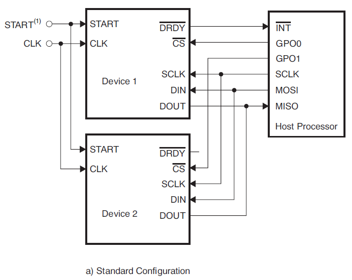
    I want to use two ADS1299 for capturing 16 channels of EEG  signal. So I'm chaining two ADS1299s together as the cascaded mode:  ADS1299 datasheet PDF33.

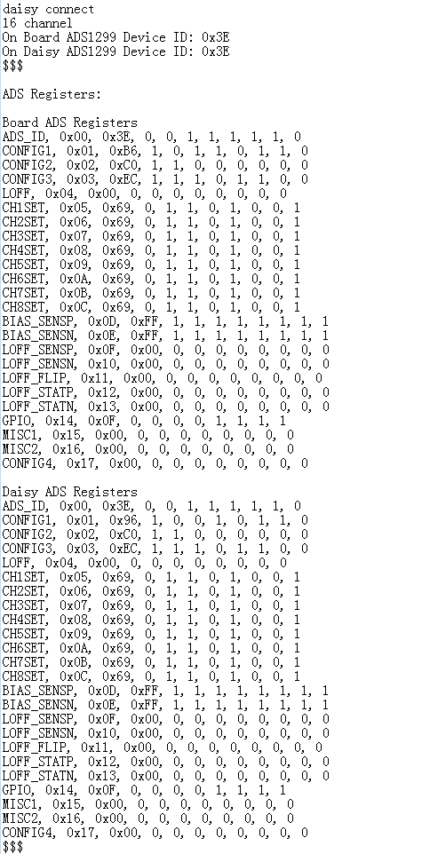
    The registers value  of Board_ADS and Daisy_ADS as follows.

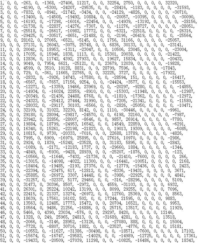
    Now I want to print out the 16 channel value of ADS(I did not connect any signal to ADS input pin).What I got as follows.

    The data looks crazy. What is wrong with it? If there is nothing signal connect to ADS1299 input pin,what value should I get from the serial port? How

    do I judgment the correctness of the data?

    Thank you.

  • Hey xyz,

    If the inputs are floating, I expect the data to be crazy. If you want to benchmark the data, change the MUXn[2:0] bits in the CHnSET registers to b'001 so all the inputs to the channels are internally shorted. Then, all the data outputs should be close to 0 V (there will be a couple of uV of noise).

    Brian
  • Hi,Brian

    I have changed the MUXn[2:0] bits in the CHnSET registers to b'001,and what I got as follows.

    (a)The value of registers.

    (b) The output data of 16 channels.The output data has changed.

    Questions.

    (a)Are the value of these registers reasonable?

    (b)Are the value of my channels data  reasonable? I am not clear about that.


    Thanks.

  • xyz,

    The registers look good.

    The non-zero values look reasonable. When the inputs are shorted, the results should correspond to the inherent voltage offset. For a gain of 24, the offset should be relative small.

    For your information, you can convert decimal to voltage by using this formula: voltage = code * Vref / [PGA gain * (2^23-1)]. The first two results of each conversion look fishy. I would look in your code to see why those results are always showing up as zero.

    Regards,
    Brian Pisani
  • Hi,Brian

    Thank you so much for your reply.

    Yes.The first two results of each conversion look fishy.I have checked my code and I found a mistake.A very long delay() function in my updateChannelData()  function,it's the reason that the first two results of each conversion look fishy.

    Now I have solved the problem and the result of testing signal looks fine.

    Later,I changed the MUXn[2:0] bits in the CHnSET registers to b'000(Normal electrode input)  to get external signal.

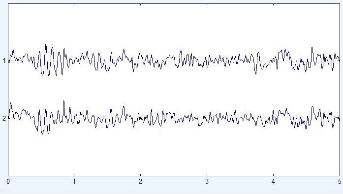
    On my circuit board,I connect the SRB2 pin of  borad_AD and the SRB2 pin of  daisy_AD together.I use a signal generator to generate a square wave signal(Frequency:10HZ,Amplitude:100mVpp)This signal was  connected to both borad_AD and daisy_AD's first channel(CH1).

    I got the corresponding two-channel data and draw with MATLAB.The result as follows.

    The result looks fine.Right?

    Are there any mistakes or shortcomings with what I have described above?

    If not,I intend to capture the real EEG data.This is really exciting.

    Thank you for some advice.

  • Hey xyz,

    That waveform doesn't look quite clean. What were the SRB2 pins connected to? Just to one another or to ground? If they are not driven actively, they will just be floating.

    Brian
  • Hi,Brian

    I connected the SRB2 pin of the first ADS1299 to the SRB2 pin of the second ADS1299. And then connected them to ground(I mean,the ground of signal generator).In my program, I have set all of the CHnSET regsiter value as 0X68(0110 1000).Yes,I have tested it again and again,and the waveform doesn't look quite clean.I don't know why.

    xyz
  • xyz,

    The ground of the signal generator is also "floating". You should connect all three nets (both device's SRB pins and the signal generator ground) to (AVDD+AVSS)/2. If you are using dual supplies, that is just the board ground. If you are using a unipolar supply, you can configure the BIASOUT pin to have a regulated midsupply by powering it but clearing all of the BIAS_SENS bits.

    Brian
  • Hi,Brian

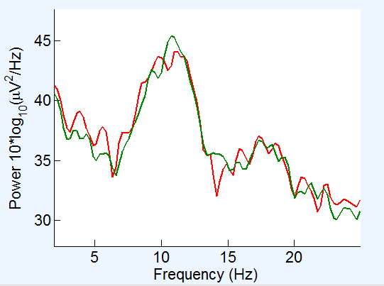
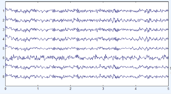
    I have done some experiment to record some EEG,such as eyes-closed alpha waves.I attached two electrode of the head(O1 and O2),the reference electrode to the left earlobe, and the bias electrode to the right earlobe. 

    I got the time-domain plot and frequency-domain plot as follows.

    The results looks good.Right?

    You really do me a great favor.Thank you very much.

  • xyz,

    It certainly looks like there is a lot of signal content in the frequency typically associated wit EEG, but I am not a neurologist ;-)

    I'm glad you seem to be getting some reliable data, though.

    Brian
  • Hi,Brian

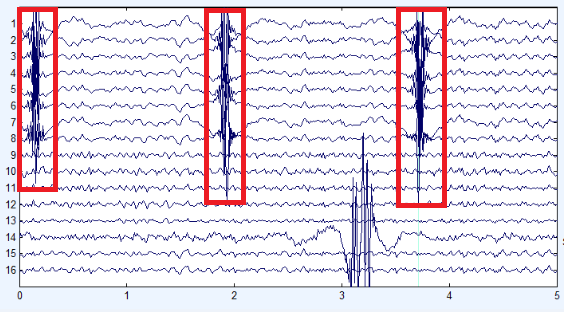
    I use my board to get 8 channels EEG and 16 channels EEG,and the waveform as follows.

    (1)8 channels.The waveform looks beautiful.And everything is fine.

    (2)16 channels.Maybe something wrong.The data of 1-8 come from the second ADS1299(daisy device),and 9-16 come from the first ADS1299(master device).As you can see,from channel 1 to channel 8,there will be a fluctuation from time to time(I marked it in the diagram).

    I do not know how it happens.This makes me very confused.Please help me.Thank you.

  • xyz,

    It could be the data is corrupted for those samples because the data is not being shifted out quickly enough. To determine this, take a look at the samples on channel 1 of the daisy chained device in that area and look to see if any of them have the sequence '1100' beginning in the middle of the samples. This is the beginning of the status word which appears at the beginning of every sample

    Brian
  • Hi Brian,

    I can get sequence'1100' on channel 1 of the daisy chained device(status word starts with 0xC0 as expected).

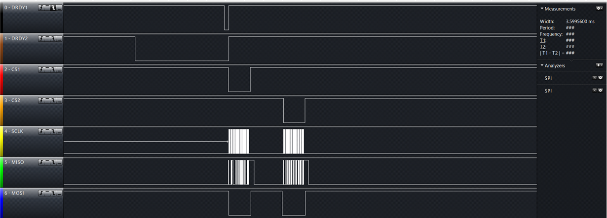
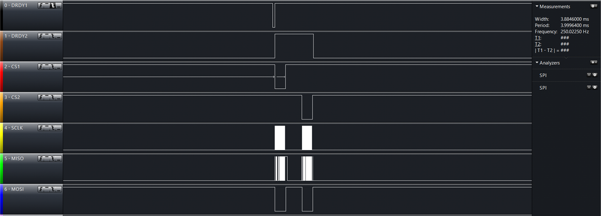
    I use a logic analyzer to get the signal.I am confused with the DRDY signal. 

    Screenshots come from two different moments.You can see the difference with the following pictures.Is it a mistake?

    With the logic analyzer source file.

    16channel-EEG.zip

  • Hello xyz,

    It looks as if the DRDY signals are not synchronized. This could be because of one or two things. First, they must be using the same master clock. All clocks have slightly different frequencies even though they may be nominally rated for the same frequency. If the device are not using the same clock source, they will eventually drift apart in the time domain. Second, the devices must be synchronized using the "START" pin. The START pin will synchronize the conversion process such that DRDY will occur at the same exact time for both devices. Are you missing either of these steps?

    Brian
  • Hi,Brian

    It looks as if the DRDY signals are not synchronized.I mean,the state of DRDY are different from the Figure 39(ADS1299 DataSheet 32).

    You pointed out two possible problems.I have checked it.

    (1)master clock.

    In my circuit,I connect CLKSEL  pin to DVDD(3.3V) of both device and  tying the CLK pins of both devices together.  And initialize the register settings as follows.

    Board ADS Register,CONFIG1, 0x01, 0xB6, 1, 0, 1, 1, 0, 1, 1, 0
    Daisy ADS Register,CONFIG1, 0x01, 0x96, 1, 0, 0, 1, 0, 1, 1, 0

    You  said the CLKSEL pin on the second device should be low.So I made a mistake?

    (2)synchronize

    You said the devices must be synchronized using the "START" pin. In my circuit,the START pin are floating of both device(when floating,the START pin is low).I use the START command to synchronize devices.As your description,I made another mistake.I mean,in multiple device configurations, the only way to synchronize devices is using the "START" pin? START command is invalid?

    By the way, I designer my circuit refer to OpenBCI 8bit.sch. I really confused with the OpenBCI 8bit.sch and the reply of you.

  • Hey xyz,

    1. If CLKSEL of both devices is high, that means they are using their own individual internal oscillators which are not synchronized. Instead, you can tie the CLKSEL pin of the daisy device low. This way, the daisy device will use the 1st device's clock as its master clock.

    2. You will not be able to use the START command to synchronize the devices. Since you have your devices configured in a cascade, you must issue the commands sequentially. For the device to be synchronized, they must be started at exactly the same time. Instead, you must use the START pins of both, tied together, and connected to the host. When you are ready to synchronize, just pull the pin high and they will begin converting at exactly the same time.

    Brian
  • Hi,Brian
    I am very sorry for the late reply.Now the DRDY signals are synchronized.
    I really appreciate your great help. Thank you very much.
  • Hi Brian and xyz ,
    I am the beginner in this field.
    Whether You can help me on how to connect each channel ,and reference electrode , and the bias electrode.
    I have try many times but never succeed any times.
    Could you help me this part?
    Send me some picture about how you attached on board.
    Thank you a lot.

    Regards, 
    Kindle Hsieh

  • Hello Kindle,

    The bias electrode should be connected to the patient to provide a dc bias to the patient. This should come from BIASOUT on the ADS1299. The reference electrode is a sensing electrode which you can connect to all the negative channel inputs of the ADS1299. This is done by connecting the reference electrode to the SRB1 pin and then making the appropriate register settings.

    Brian
  • Hey Brian,
    Thanks for your reply.
    Part1:
    I want to use STM32FXXX to be my mother board (MASTER) and ADS1299 EVM as slave.
    I think SRB1 and MISCI is controlled by the APP providing on the TI website.
    How can I connecting to SRB1 pin?
    Part2:
    I have see lots of information about Internal Reference and External reference on the user guide.
    So Am I using external reference( because I need to connect on my ears) ? D0 I need to install JP3?
    Part3:
    I have seen the "Register Map" on page 26.
    I hope I can get the EEG signal from the every channel via SPI.
    So whether the address of CHxSET is the target which I want, or not?
    What is the way I need to use to get the signal? (EX: Frequency?, How many bits I need to read on times. .... )

    Thanks for your patience reading my question.
    Please help me figure out the problems.

    Regards,
    Kindle Hishe
  • Hello Hshieh,

    I think a lot of your questions could be answered if you were to look at the datasheet for the ADS1299. The ADS1299EEGFE is an evaluation module for that device, so the user's guide does not discuss a lot of the technical details of the operation of the ADS1299. You can find that document here. Please let me know if there is something you still do not understand after reviewing that document.

    Brian

  • Hello Brian,
    Thanks for keeping in touch with we.
    Actually, I have already read this two paper many times but I still can't figure my problem out.
    So, I give you page and ask some questions which have bothered me some weeks.

    Maybe the problem is I'm not  student in this field.

    Please help me and just take me like a fool. 
    Tell me the detail how can I do and answer those question above last conversation.
    I know there are basic, please help me.
    Thanks again.

    Kindle Hsieh

  • Kindle,

    First, there two different references that are unrelated when talking about the ADS1299. The first is the reference voltage for the ADC. All analog to digital converters require a reference voltage to which the input voltage is compared to generate the digital output. When the user's guide is talking about internal and external references, they are talking about this reference.

    The other reference is the reference electrode. This is specific to EEG applications. The reference electrode is one electrode that all the other electrodes are measured against. As you know, voltage of one thing can only be measured with relative to something else. In some EEG applications, the voltages of all the electrodes are measured relative to one "reference" electrode.

    Now let me answer your questions:

    1. The SRB1 pin can connect to the negative input to all the channels. This is intended as the input for the reference electrode. On the EVM, you can place a jumper on pins 1 and 2 of JP8 which connects SRB1 to pin 6 of JP25. You can connect some external source to that pin.
    2. You can simply use the internal reference voltage. In fact, the circuit for the external reference is not installed on the board so you could not use it anyway.
    3. The data is read from the device by waiting for the DRDY pin to go from high to low, and then reading the conversion data serially using SPI. If you are unfamiliar with the SPI interface, there is plenty of material online that can teach you what it is. The datasheet has the details of how to communicate with the ADS1299 using SPI. The DRDY pin will go from low to high at a frequency corresponding to the data rate. The data rate can be configured in the CONFIG1 register.

    Regards,

    Brian Pisani

  • Hi Brian,
    Thanks for your teaching. You are so kind and really help me a lot.

    I have some questions here, please help me.
    You have talk about DRDY pin I know it and I have read the information about it.
    But I still can't understand if I have connecting CS , did I need to connect DRDY at the same time?
    It seems that I don't need to make them together at the same time from your words.

    And could you tell me the register address for saving value of every channel. I can't make sure Figure.28 on User Guide is right what I need or not.
    there are the problems what I have met. Please help me.
    Thank you.

    Kindle Hsieh

  • Kindle,

    The CS pin is an input and the DRDY pin is an output. You should not connect them. CS is the chip select pin which is common to most SPI interfaces. When the pin is low, the device is enabled for communication. DRDY is an interrupt pin which will indicate to the host that new data are available and that the host should retrieve it.

    The ADS1299 cannot "save" data. Each time it generates a conversion result, your microcontroller must retrieve the data using SPI.

    Regards,
    Brian
  • Hi Brian,
    Your advice give me lots of help.
    I have some problems about " Initial Flow at Power-Up ".

    1. Can you teach me how to take sure VCAP1 is large than or equal to 1.1V?
    How can I write my program algorithm to make sure this situation?

    2. How can I do to  "set START = 1" in this figure?
    For example, 9.4.1 say " Pull the START pin high for at least 2 tCLK periods, or send the START command to begin conversions. "
    How can I use the START command? I know Table 10 have command, but I still don't understand how to use.
    How can I make sure how big my "DVDD" is and " tCLK " ?

    Thanks again for you help.

    Kindle Hsieh

  • Hello Kindle,

    1. Refer to Figure 25. Analyzing this circuit shows the bandgap voltage is 1.2V. The voltage at VCAP1 will behave like an RC circuit like you studied in school. From the instant that the bandgap is powered to 1.2 V, the voltage at VCAP1 will be VCAP1 = 1.2(1 - e^t/(RC)). From there you can solve for when VCAP1 = 1.1V. It turns out to be roughly 2.5 seconds. You should also add a little margin since R and C may not be exactly equal to their nominal values. I'd say that to ensure VCAP1 is at least 1.1V, you should wait 3 seconds from when the the analog supply is first applied before issuing the reset pulse.
    2. Setting START = 1 is as simple as setting the START pin to logic high or issuing the START command. Issuing the START command is done by sending the 8 bit START opcode to the ADS1299 via SPI. DVDD is the digital voltage. You can find this voltage by probing it with a multi-meter. The master clock period tclk is nominally 1/2.046e6.

    Brian

  • Hi Brian,
    Thanks for your direction.
    I have following your advice about how to initialize the ads1299 chip, but I have some problems at the testing mode.

    I just plot the all signal directly only.
    I can't get the square wave.
    Can you tell about how to get the square wave in detail. 
    Like as, I get the 24bits data from the chip, and then I should follow which steps to decode my signal et.
    Thanks for your direction again.

    Regards,
    Kindle Hsieh


  • Hello Kindle,

    Make sure CONFIG2 = 0xD0, CONFIG3 bit 7 is 1, and CHnSET bits 2:0 to 101. If they are, then please describe how you are translating the binary output to voltage.

    Brian
  • Hello Brain,

    Thank for your patient and help again.
    The attachment is the detail what I do and my problems.

    Kindle Hsieh

    mail.docx

  • Hello Kindle,

    First, not all the registers will be programmed. To write 11 registers, you need to set 0x0C as the "number" rather than 0x0A. Instead, the write should look like 0x42 0C D0 E0...

    Second, can you capture the SPI signals with an oscilloscope or logic analyzer during a data read? I want to see if the protocol is correct. Please probe DRDY, CS, SCLK and DOUT.

    Brian
  • Hi Brian,

    Thank for your previous help.
    I almost finish my chip setting. Now, I can receive the test signal from my ads1299 chip. This glad Is thanks to you!

    But I can’t receive the right EEG signal from the channel.
    I think the problem is on Register setting again.
    There are lots of setting mode but no one I can understand.

    Please teach me how to set every mode on registers for EEG signal in normal condition.
    I have try a lot but I still don’t have any idea in my mind.
    Please help me.
    I use reference from chip (so I only need to connect one elector end to one ear right?) .

    I also want to know the specific meaning about lead-off, bias setting… they really feel very frustrated.

    Thanks for your help again. You really are give me a hand.

    Kindle Hsieh

  • Hello Kindle,

    To simply measure a signal, start by investigating your bias amplifier settings. This app note contains information about the "RLD" amplifier on the ADS1298, but it's function is the same as the bias amplifier on the ADS1299. The bias amplifier output should connect to the bias electrode which is sometimes connected behind the ear. In the app note, they refer to ECG electrodes, but their function should be the same as EEG electrodes except they are placed on the head rather than across the chest.

    Regards,

    Brian

  • Hi Brian,

    Thank you again, you are really a good helper.
    But I still have lots of problems.

    The hyperlink which you give me only give me the information about lead-off.
    And I still can't understand why I need lead-off to monitor my device.
    The most important thing is I want I can get the clear EEG signals.
    But my result is so terrible, as the follow.

    I have get the test signal successfully. So I can make sure my chip can work normally.

    The Image 1. is under the situation which I only set channel 1 to 3 as normal, and the others are power-down.
    But I get lots of noise even I didn't touch it, and there is also no reactions when I touch the electrode from channel 1 to 3.
    The others channels I think they must be 0 voltage or just very small voltage but we can see the value still huge from the Image 1.

    There are the registers setting:
    device.write(0x11); //SDATAC
    wait(4*tclk);
    device.write(0x41); //from 01h to 0Eh.
    device.write(0x0D); // total 14-1 registers.
    device.write(0xD2); // configure 1.
    device.write(0xD0); // configure 2.
    device.write(0xEC); // configure 3.
    device.write(0x00);
    device.write(0x00); // channel 1
    device.write(0x00);
    device.write(0x00);
    device.write(0x80);
    device.write(0x80);
    device.write(0x80);
    device.write(0x80);
    device.write(0x80); // channel 8
    device.write(0x00); // BIAS_SENSP (we need all to be 1.)
    device.write(0x00); // BIAS_SENSP (we need all to be 1.)
    device.write(0x4F); // 15h.
    device.write(0x00); // Only MISC1.
    device.write(0x20); // MISC1.
    device.write(0x10); //RDATAC

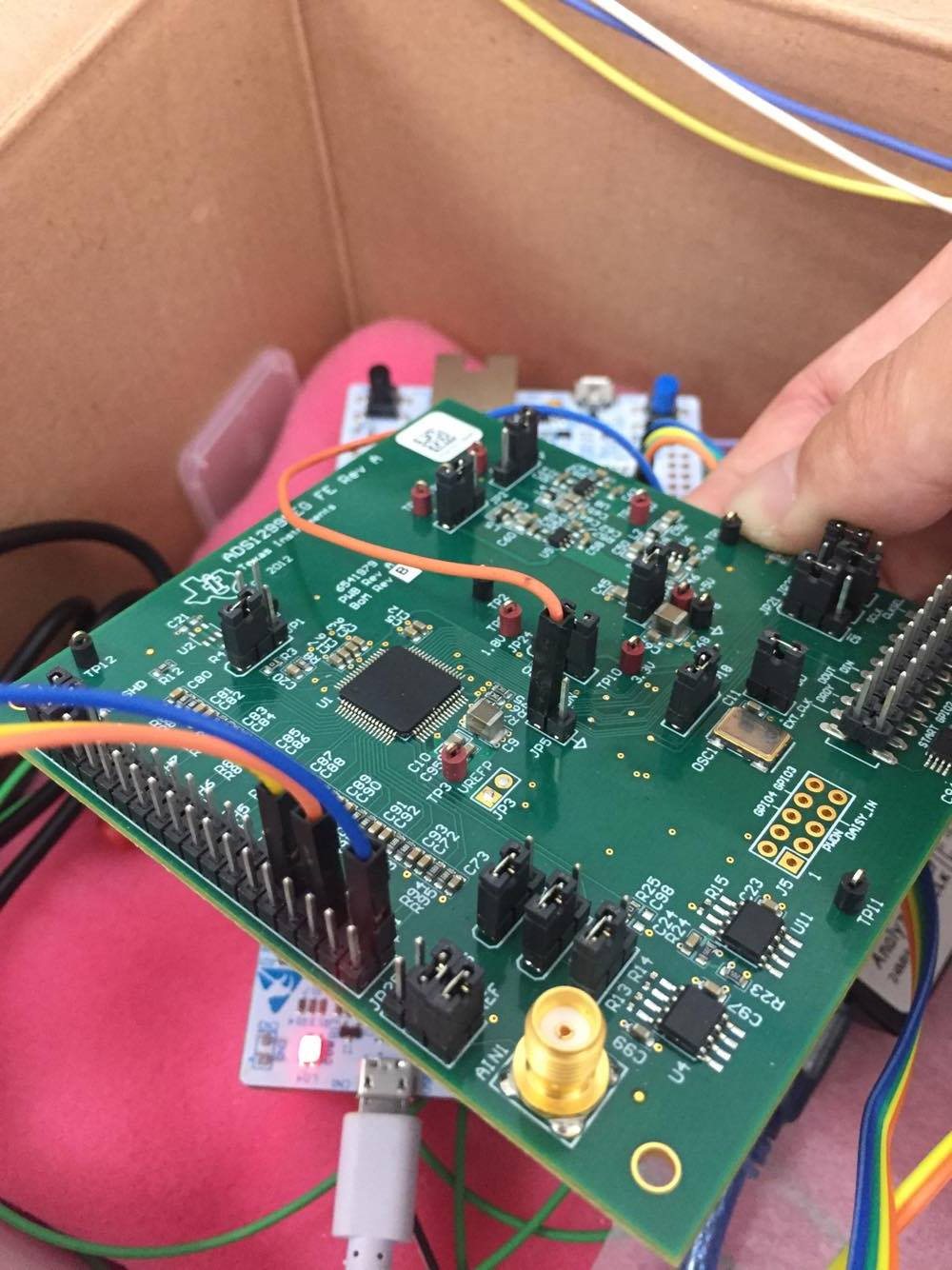
    Image 2. is about how I connect the device.
    Blue one is connect to my ear as bias reference.
    Orange and yellow is connect to my brain channel (I just user my hand to touch it , not really connect on my brain) .
    I really so stupid at this field.
    If there are any wrong, please help me.  Thank you.
    You are so kind.

    Kindle Hsieh

    Image 1.

    Image 2.

  • Hello Kindle,

    That app note is not about lead-off detection. It is about using cancelling common-mode interference using the RLD amplifier on the ADS1298 which is the same as the bias amplifier on the ADS1299. Common-mode interference is the source of your issues. Please read that application note. I recommend that you implement the strategy it describes. If you have questions about the theory in the app note, please post them here.

    Brian
  • Hi Brian,

    I have read it lots of time already.
    But I still can not understand what it mean.
    Can you tell me directly about which section I should try, or just tell me how to do?
    I think it will be more helpful.

    And I think my problem maybe also on how to connect correctly the electrode.
    I hope you can answer me this part, it block my road to implement the strategy on the app note.

    Could you also answer me why I have closed the other channels, but I still have the signal?
    And, can I make the experiment without connect on my head?  I just want to test the channel is right or not.

    I really want to solve these problems, please give me some practical help.
    I work hard and learn effort as you.  Please teach me.  
    Thank you.

    Kindle Hsieh

  • Hello Kindle,

    The idea of the app note is that the "Right Leg" electrode (known as the "ground electrode" in EEG systems) serves 2 purposes. One is to bias the patient. Without a DC bias, the patient is floating and his/her signals cannot be measured. The other reason is that it forms a common-mode rejection feedback loop. There is a lot of common-mode interference in medical applications from the environment (lights, fans, motors, etc.). To help counteract this problem, you can utilize the bias amplifier to sense the common-mode from the electrode inputs, and output the inverted common-mode and apply it to the patient as an attempt to cancel it.

    To use this, you must power on the bias amplifier and then allow the electrode signals to serve as inputs to the bias amplifier. Figure 38 in the datasheet shows the switches that connect from the PGA outputs to the bias amplifier. Then the BIASOUT pin should connect to the ground electrode which is connected to the patient.

    As for the electrode placement, I do not know exactly where to place them because I am an electronics expert, but I am not a neurology expert. Perhaps you can find out more about proper EEG electrode placement on the web.

    Brian
  • Hi Brian,

    Thanks for your advice.

    1.
    Now, I think maybe I saw the very huge voltage which is resulted by wrong decode. (As the picture before.)
    I reference this article to decode the 24 bits data format from the device.    Can you tell me that is right to use this way or not?
    2.
    And could you give me some advances about how to make sure the output voltage from each channel is right or not ?
    3.
    My problem is I can't see any voltage change when I touch any channel., so I need a good way to fix it.
    Thank you.

    Kindle Hsieh

  • Hi,Kindle Hsieh

    I have received your email.
    You ask me three questions as follows
    (1)Are you use the ads1299 evm?
    (2)Can you teach me how to install the electrode on the board?
    (3)And why you can get so clear channel signals?

    what I do as follows.
    (1)NO,I also use ADS1299 chip .
    (2)I attached two electrode of the head(O1 and O2),the reference electrode(SRB pin on the board) to the left earlobe, and the bias electrode(Bias pin on the board) to the right earlobe.
    (3)The time-domain plot and frequency-domain plot as I post,the waveform obtained after filtering, not the original waveform.

    xyz
  • Kindle,

    1. That article is helpful. Also section 9.5.1 in the data sheet provides the formula to convert codes to volts.

    2. This will just have to be done by testing. You can use the integrated test signal to make sure your code is translating the ADC output to the correct voltage. Then you will know that the voltage you are seeing at the output of the ADC corresponds correctly to the input voltage.

    3. I am still convinced your problem is related to patient biasing. The integrated bias amplifier connected to the ground electrode should help to fix this issue.

    Brian