This thread has been locked.

If you have a related question, please click the "Ask a related question" button in the top right corner. The newly created question will be automatically linked to this question.

ADS 1248 - 4 Wire RTD - ADC Reading Changes day to day

Other Parts Discussed in Thread: ADS1248, ADS1247

Dear All,

I have an issue with my ADS 1248 circuit. I have a simple ratiometric circuit, exactly like a 4 wire RTD setup. 1 mA flows through IEXC1 with 1.2kohm across REFP0 and REFN0. I have put a 430 ohm resistor across AIN0 (positive) and AIN1 (negative).

The controller that I am using is an Arduino Uno with the Flydroid ADS1248 library. I can get all the registers to read. Using the external ref test, the ADS reads about 1.21V across REFP0 and REFN0, which is expected.

I am using a PGA gain of 2. 

The measurement precision is >0.05% if I take the result when the device is switched on and sampling, the 24bit value is ~ 5BD3E7. The issue I have is that day to day or when the device is put off and on for an hour or so, the reading of the ADC has a large difference, in the order of 1%. 

I have built a second circuit with a PIC18 controller on a printed circuit board and I am having the same issue.

Can someone please help?

Kind Regards,

Shiv

  • Hi Shiv,

    welcome to our forum.

    Could you share the schematic with me and also the exact way how you calculate the voltage and temperature from the output codes?
    Did you use a precision, low-drift 1.2kOhm resistor?
    Keep in mind that self heating due to the current flowing through the resistors can change your results.

    Regards,
  • Dear Joachim,
    Thank you for your reply. I think that you are correct I have been playing around with resistors and it appears to change the outcome. Do you have any suggestions as to the specifications of the resistor to use?

    Thanks,
    Shiv
  • Dear Joachim,

    Thank you for your reply. I think that you are correct, I have been playing around with different resistors and it appears to alter the outcome. Do you have any suggestions about the appropriate resistor to use?

    Kind Regards,

    Shiv

  • Hi Shiv,

    there are multiple things you can try.

    If self-heating is really the concern then you could simply use a smaller excitation current or use resistors with higher power ratings.
    In order to simulate an RTD we usually use a set of high-precision resistors. We measure their exact value with a >=6.5digit DMM shortly before connecting them to the circuit.

    Why I was asking for your calculation is, because many customers implement the circuit in a ratiometric fashion, but then do not utilize it when implementing the code.

    Regards,
  • Hi Joachim,

    Thanks for your reply. I have used a higher power resistor and and I have reduced the current to now 100uA. Between yesterday and today the measured resistance of the fixed resistor changed from 164.0 ohms to 164.8 ohms. These resistors have a temperature coefficient of +350ppm per deg C and the room temperature is 1 degC lower today, so it is appears not an effect of temperature as it is in the wrong direction. I have changed the reference resistor to ~4.7K(+-5%) 0.5W resistor and the measurement resistor is ~160R 0.5W (+-5%).

    My calculation of resistance is as follows : [(ADC Value) *Rref] / [ (2^(24-1)) * (PGA Value)]

    Rref = 4700; PGA Value = 2; ADC Value is read from the ADS1248;

    My code is arduino:

    // To set up registers:

    ADS.SetRegisterValue(MUXy1, BCS1_1 | MUX_SP2_AIN0 | MUX_SN2_AIN1);
    delay(500);
    ADS.SetRegisterValue(MUXy1, VREFCON1_ON | MUXCAL2_NORMAL | REFSELT1_REF0); // Set Internal Ref ON , Normal operation MUX; Set Reference to REFP0 and REFN0


    delay(500);
    ADS.SetRegisterValue(IDAC0, IMAG2_100); // IDAC at 100uA current
    delay(500);
    ADS.SetRegisterValue(IDAC1, I1DIR_IEXT1 | I2DIR_OFF); // IDAC1 Current output ON IEXC1, IDAC2 OFF
    delay(500);
    ADS.SetRegisterValue(SYS0, PGA2_2 | DOR3_5); // PGA set at 2, 5SPS

    //Read from chip

    void loop() {

    adz0 = ADS.GetConversion();

    adz1 = (adz0*4700)/8388608/2;

    Serial.print("Resistance = ");
    Serial.println(adz1, DEC);

    }

    // C functions from flydroid for ADS1248

    // function to get a 3byte conversion result from the adc

    long ads12xx::GetConversion() {
    int32_t regData;
    //waitforDRDY(); // Wait until DRDY is LOW
    SPI.beginTransaction(SPISettings(SPI_SPEED, MSBFIRST, SPI_MODE1));
    digitalWrite(_CS, LOW); //Pull SS Low to Enable Communications with ADS1247
    delayMicroseconds(10); // RD: Wait 25ns for ADC12xx to get ready
    SPI.transfer(RDATA); //Issue RDATA
    delayMicroseconds(10);
    regData |= SPI.transfer(NOP);
    //Serial.println(regData, HEX);
    delayMicroseconds(10);
    regData <<= 8;
    regData |= SPI.transfer(NOP);
    //Serial.println(regData, HEX);
    delayMicroseconds(10);
    regData <<= 8;
    regData |= SPI.transfer(NOP);
    Serial.println(regData, HEX);
    delayMicroseconds(10);
    digitalWrite(_CS, HIGH);
    SPI.endTransaction();

    // function to write a register value to the adc
    // argumen: adress for the register to write into, value to write
    void ads12xx::SetRegisterValue(uint8_t regAdress, uint8_t regValue) {
    #ifdef ADS1248
    if (regAdress == IDAC0) {
    regValue = regValue | IDAC0_ID; // add non 0 non-write register value IDAC0_ID
    }
    #endif
    uint8_t regValuePre = ads12xx::GetRegisterValue(regAdress);
    if (regValue != regValuePre) {
    //digitalWrite(_START, HIGH);
    delayMicroseconds(10);
    waitforDRDY();
    SPI.beginTransaction(SPISettings(SPI_SPEED, MSBFIRST, SPI_MODE1)); // initialize SPI with SPI_SPEED, MSB first, SPI Mode1
    digitalWrite(_CS, LOW);
    delayMicroseconds(10);
    SPI.transfer(WREG | regAdress); // send 1st command byte, address of the register
    SPI.transfer(0x00); // send 2nd command byte, write only one register
    SPI.transfer(regValue); // write data (1 Byte) for the register
    delayMicroseconds(10);
    digitalWrite(_CS, HIGH);
    //digitalWrite(_START, LOW);
    if (regValue != ads12xx::GetRegisterValue(regAdress)) { //Check if write was succesfull
    Serial.print("Write to Register 0x");
    Serial.print(regAdress, HEX);
    Serial.println(" failed!");
    }
    SPI.endTransaction();

    }

    }

    I have not included all the code as it is quite long, but i you need any more info please let me know.

    Thank you I really appreciate your help.

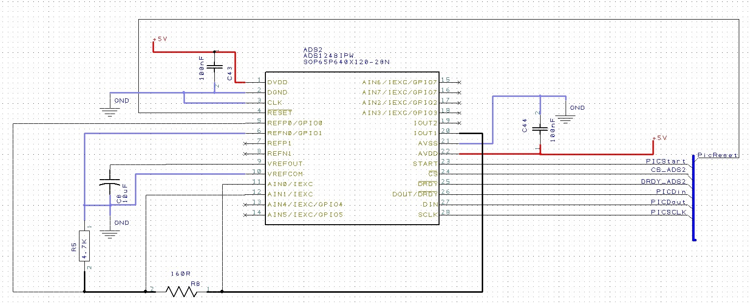
    My schematic is :

  • Hi Shiv,

    thanks a lot for all this additional information.

    Does your reference resistor R5 also have a temperature coefficient of 350ppm/°C? We usually use precision resistors with a temperature coefficient between 5ppm/°C and 50ppm/°C in this place.
    I think if you really want to measure the accuracy of the measurement system you would have to know exactly what the resistor values R5 and RB are. That is why we either use really high precision resistors to simulate an RTD or at least measure the exact resistor value with a high-end DMM every time before you run measurements.

    Your calculation looks correct.
    I didn't look through your code in detail yet, but I doubt this is the issue in your case.

    With a RREF=4.7k and IDAC=100uA your reference voltage will be really low. Actually below the allowed VREF range of ADS1248.
    I recommend to set the reference voltage somewhere close to mid-supply. Means either increase RREF even further or increase the IDAC current to 500uA. You should also be able to use much higher gain.

    The schematic looks okay in general as well. I would recommend to place a differential cap across the reference inputs REFP0/REFN0.
    Also a differential RC filter on the AIN0/AIN1 inputs would be something I would recommend.

    Regards,
  • hi Shiv,

    Have you fixed this problem?I also meet this issue,can you give me some suggestions?

  • Hi user4904810,


    From the last post, it looks like a lot of the noise is coming from the drift of the resistors. As Joachim has mentioned, we use precision resistors that have extremely low drift. Any error in the reference resistor is directly reflected as an error in the measurement.

    With a 24-bit ADC, you can easily see any large reference drift drift. I've run similar tests and I'll use resistors that have a drift of 5ppm/°C or less. From the original poster, a resistor of 350ppm/°C will change 0.035% with a 1.0°C change in temp. This change is easily seen when making a measurement. If the reference resistor drifts higher by 0.035%, then the measurement looks 0.035% smaller. In the end, the reference resistor accuracy and drift is very important to the measurement.


    Joseph Wu