This thread has been locked.

If you have a related question, please click the "Ask a related question" button in the top right corner. The newly created question will be automatically linked to this question.

ADS1247 3Wire RTD Reference Design

Other Parts Discussed in Thread: ADS1247, ADS124S06, ADS1248, ADS124S08

Hello,

I am looking for 3 wire RTD reference circuit with ratio metric configuration. I want to use 2.048V Vref voltage instead of current excitation method. PT1000 is planned to be used in the design. Range of temperature -80°C to ambient 25°C.

Kindly support on this design.

Regards,

JG


  • JG,


    I would suggest you read the following example design:

    www.ti.com/lit/ug/slau520a/slau520a.pdf

    While this design is for a PT100 (and yours is for a PT1000), the design procedure should be similar. Also, the datasheet for the ADS1247 has a write up that also describes the design of a temperature measurement system using the PT100.


    Joseph Wu
  • Hi JG,

    we usually promote the current excitation method using the integrated excitation current sources for RTD applications. This is what is shown in the datasheet and the TI Design that Joseph was referring to.

    However a voltage excitation method using the internal voltage reference can certainly be implemented as well. It will require more measurement steps and therefore is a little more cumbersome.

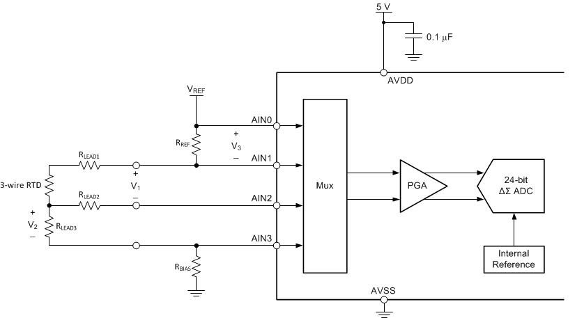
    The following circuit shows a principle implementation (no input filters and protection circuits shown), which uses the internal voltage reference both for excitation of the RTD and the ADC conversion.
    You need to take three measurements to measure the RTD resistance including lead resistance compensation:
    1. Measure voltage V3 to derive the current flowing through the RTD: I_EXC = V3/R_REF
    2. Measure voltage V2 to derive the lead resistance: R_LEAD = V2/I_EXC
    3. Measure V1 to derive the RTD resistance: R_RTD = V1/I_EXC - R_LEAD

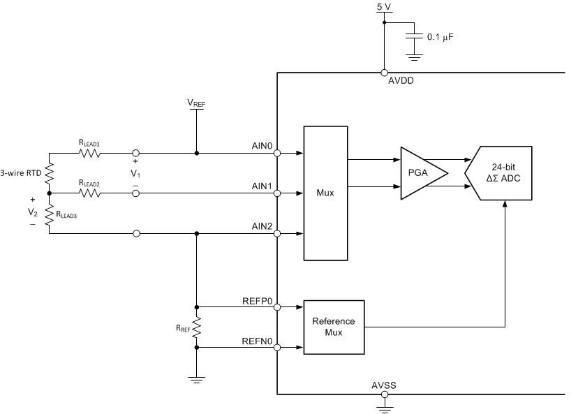
    The following circuit might be a better solution though for voltage excitation.
    In this circuit the internal voltage reference is used for excitation, however the voltage across R_REF is used as the reference voltage for the ADC conversion.
    This way you only need to run two measurements while also using a ratiometric measurement approach.
    1. Measure V2 to determine the lead resistance
    2. Measure V1 to determine R_RTD

    For 2- and 4-wire RTDs the voltage excitation method is much easier to implement.
    You would simply build a voltage divider consisting of the RTD and a precision reference resistor, R_REF which you excite with the voltage reference, V_REF.
    The RTD resistance is then derived by measuring the voltage across the RTD and using the following formula: V_RTD = V_REF * (R_RTD / R_RTD + R_REF)

    I also wanted to make you aware of a new device which we will release in the next few weeks. It is the next generation of ADS1247, called ADS124S06.

    Regards,

  • HI Joachim,

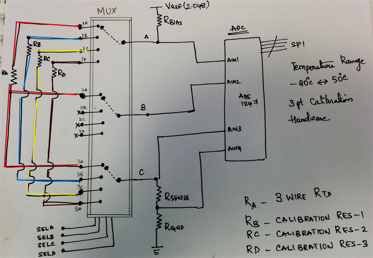
    Thank You for the reply and suggestion. Based on the suggestion, we have made few steps forward, i have attached a modified application circuit which i am planning to simulate over next few days.

    Per application we need to also incorporate 3 Point hardware calibration circuit/resistors in the design for which i have used an analog mux and tired to switch all 3 resistors to ADC channel. (This happens to be only once during board power on condition).

    For the sake ease of understanding, i have marked colors about the current (Iexc paths) through the nodes.

    I will be using Rsense resistor to measure I rtd and Rgnd resistor will hold good Vcm of input channels. I will have to flow a max of 300uA excitation current into sensor as per M/F recommendation to avoid self heating.

    I tried to use which has min sw ON resistance.

    Please evaluate the circuit and suggest anything which is missing or which can make circuit work.


    Please see my attachment.

    Regards,JG

  • Hi JG,

    thanks a lot for your feedback and for sharing your proposal with me.

    Your implementation should work in principle, however I think it is more complicated than it would need to be.
    I have actually rarely seen a customer using three different calibration resistors for calibration purposes on a board. Do you have such stringent accuracy requirements?

    One thing you will need to watch out for is the leakage current and on-resistance of your MUX. This can affect your overall accuracy. For example if your MUX has some leakage path to adjacent channels, then the current you measure across R_Sense will not be exactly the same current that flows through the RTD and thus introduce an error.
    In your proposal you could measure the current across the R_Bias on the high side instead. That way you would save at least one resistor.
    Also all connections on point C could be tied together in my opinion without the need for a MUX.

    Are you opposed to using a true ratiometric implementation as shown in my 2nd circuit?
    That way you would only need R_Sense and no R_Bias resistors at all. You would also save one measurement step as you do not need to measure the excitation current separately then.

    The least effort would be to use the integrated excitation currents as mentioned by Joseph. That way you would most likely not even need an external MUX when using ADS1248.
    With our new ADS124S08, which is the successor of ADS1248, you would definitely not need an external MUX then.

    Regards,