This thread has been locked.

If you have a related question, please click the "Ask a related question" button in the top right corner. The newly created question will be automatically linked to this question.

Noise of ADS1298R on the board

Other Parts Discussed in Thread: ADS1298R, TEST2

Hi,

      I test the noise with my own designed board.

      with the same Condition:

      1) +-2.5V supply

      2) Internal 2.4V Reference

      3) HR mode

      4) GAIN=6

      5) 1000 samples were taken to calcuate the uVpp and uRMS according to "8.1 Noise Measurements" in the ADS1298R datasheet

      Test1:

      Condition: Set all CHnSet registers to "Input shorted"

      Result:


My Board

(uRMS) uVpp

(0.58) 3.84

      The result is quite near with the value "(0.6) 3.5" in Table1 in the  "8.1 Noise Measurements" in the ADS1298R datasheet.

      Since the input is shorted internally in the chip, I think this shows the input-referred noise that is introduced in the chip.

      Test2:

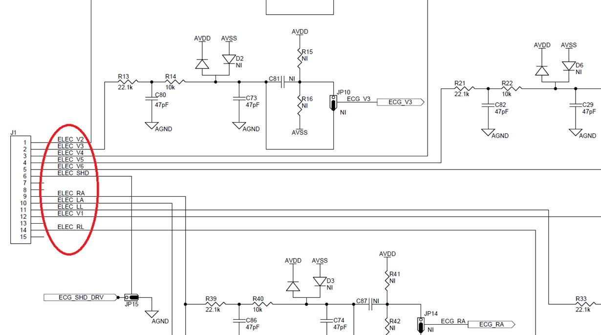
      Condition: Set all CHnSet registers to "Normal electrode input", short all the leads (except RLD) to GND at the sockets where the leads are connected to the board.

      Result:


My Board

(uRMS) uVpp

(6.2) 27.9

      I think this shows the input-referred noise that is introduced on the board. While the result in Test1 shows the input-referred noise that is introduced in the chip.

     Question 1: Is the vaule of 27.9uV in Test2 reasonable? Is this on board noise too large?

     Question 2: Is there any on board noise test result that can be taken for reference?

     Question 3: What is the minimum on board noise that could be got?

     Question 4: I think 27.9uV is still too large, since the ECG vpp is only 1mV and the details of the waveform are just a few tens of uV. Is there any advice to improve the noise on the board?

      Thank you.

Frank

  • Hey Frank,

    There are a few causes of noise that can occur outside of the IC.

    1. Thermal noise in resistors (otherwise known as Johnson-Nyquist noise). Assuming you have an RC filter on the inputs, the RMS noise that comes from those resistors in the filter is equal to sqrt(kT/C) where k is Boltzmann's constant, T is the temperature in Kelvin, and C is the capacitance in the RC filter (R is not a factor in this expression because it cancels out in the algebra - I won't prove that the expression is correct mathematically, but you can do a web search if you don't believe me). One way to reduce this noise is to make C larger.
    2. Power line utility interference. If there are fluorescent lights in the room you are taking the measurements, it's likely that some of the utility signal is coupling capacitively on to your board. You can verify this by taking an fft of the data you collected and checking for a peak near 50 or 60 Hz. This can be reduced in 2 ways. The first is through the use of the integrated right-leg drive functionality on the ADS1298R board. This feature will actively attempt to cancel any common-mode signals that appear at the inputs. The second way is to implement a digital notch filter at the problem frequency to attenuate it even further.

    Can the noise you see be accounted for by either/both of these sources?

    Regards,

    Brian Pisani

  • Hi Brian Pisani,

            Thank you very much for reply.

            1. But I don't have RC filter on the board, my schematic is based on the schematic of ADS1298RECG-FE. 

            2. Yes the right-leg can improve the noise, but in my test, all the leads except RLD are shorted to GND. The RLD has nothing to drive in the test.

            I take some more experiments in different time with my board and with ADS1298RECG-FE

            Test1:

            Condition: All of the test are in this condition: Set all CHnSet registers to "Normal electrode input", short all the leads (except RLD) to GND at the sockets where the leads are connected to the board.

    Test

    My Board

    ADS1298RECG-FE

    1

    (2.49) 8.66

    (0.59) 3.71

           In the table, the uVpp and uRMS are the average value of CH2-CH8 channels.

           The noise of my board is bigger that the noise of the ADS1298RECG-FE. While the noise of ADS1298RECG-FE is neally the same as the internal shorted situation "(0.6) 3.5".

           I take the average of CH2-CH8, because my CH1 has great noise. This will be discussed later.

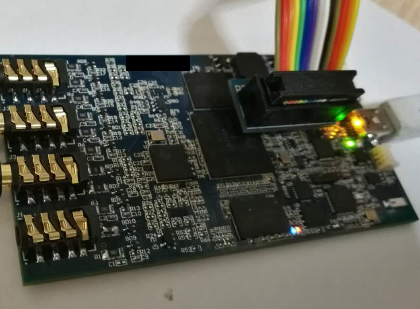
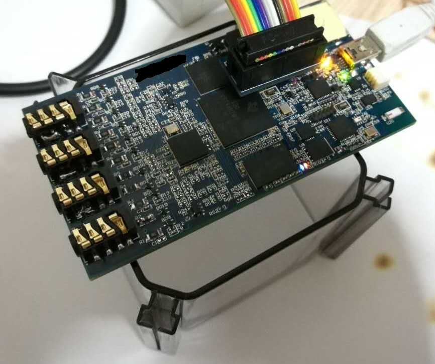
           In Test1 my board is put on a A4 paper on the desk as shown below.


        Test2:

        Condition: My board is put on a plastic support. Other condition is the same with Test1.


           Result:

    Test

    My board

    ADS1298RECG-FE

    2

    (0.38) 2.38

    (0.56) 3.68

           Test3:

           Condition: Set "Internal shorted". Other condition is the same with Test2.

           Result:

    Test

    My board

    ADS1298RECG-FE

    3

    (0.60) 3.79

    (0.58) 3.75


          Put the Results together:

    Test

    My board

    ADS1298RECG-FE

    1

    (2.49) 8.66

    (0.59) 3.71

    2

    (0.38) 2.38

    (0.56) 3.68

    3

    (0.60) 3.79

    (0.58) 3.75

    The above tests are repeated many times, and the result shows the same phenomenon.

    Disscussion:

    Compare Test1 & Test2: It seems put the board on the desk with support will introduce much more noise. (ADS1298RECG-FE has a support in Test1 and Test2, so the results are the same.) I think maybe that is because of mechanical vibration when the computers\instruments are working. But I didn't find any theroy that the mechanical vibration will convert to electric noise.

    Question1: What is your suggetion for explaining this phenomenon?

    Compare Test2 & Test3: It seems my board has even smaller noise when external shorted than internal shorted.  But the ADS1298RECG-FE has the same noise value when external shorted and internal shorted.

    Question2: Is that possible that "external shorted" has smaller noise than "internal shorted"? What is your suggetion for explaining this phenomenon?

    --------------------------------------------------------------------------------------------------------------------------------------------------------------------------------------------------------------------

    Discussion on Channel 1

    The difference betwen My Board and ADS1298RECG-FE is:

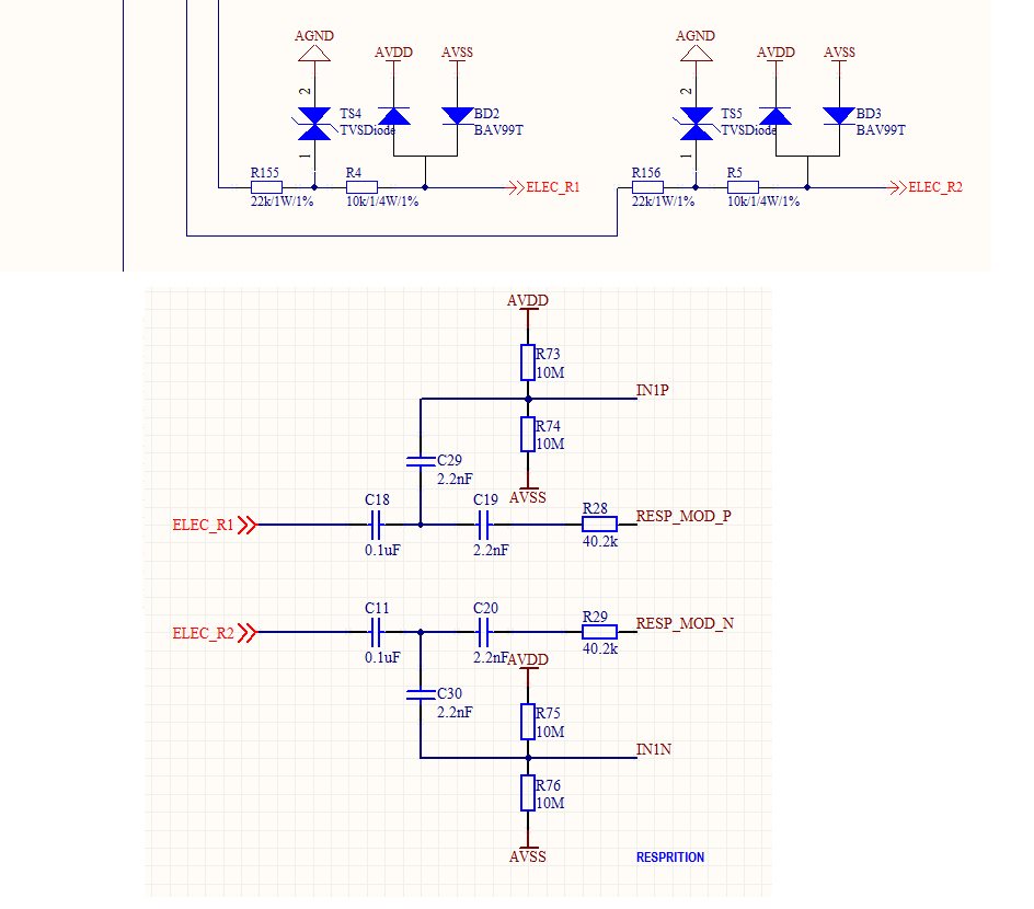
    1) I take protect circuit for ELEC_R1 and ELEC_R2, while  ADS1298RECG-FE directly connect ELEC_R1 and ELEC_R2 to C18 and C11

    Question3: Does ELEC_R1 and ELEC_R2 need the protection circuit? 

          2) Althrough there are protection diodes in the schematic of  ADS1298RECG-FE, but the board didn't take them on. While I have them on board.

           And this is the details of each channel:

    ADS1298RECG-FE

    CH1

    CH2

    CH3

    CH4

    CH5

    CH6

    CH7

    CH8

    Avg2-8

      uVpp

    3.43

    3.39

    3.86

    3.67

    4.10

    3.53

    3.86

    3.53

    3.71

      uRMS

    0.54

    0.57

    0.62

    0.60

    0.57

    0.57

    0.60

    0.58

    0.59

    My board

    CH1

    CH2

    CH3

    CH4

    CH5

    CH6

    CH7

    CH8

    Avg2-8

     uVpp

    57.22

    2.05

    2.38

    2.48

    2.24

    2.15

    2.53

    2.86

    2.38

      uRMS

    11.44

    0.33

    0.38

    0.40

    0.39

    0.38

    0.38

    0.39

    0.38

    As can be seen, my CH1 has much great noise. I think the only difference is my CH1 has protection circuit.

    Question4: Is there any way to have the protection circuit while still have low noise?

        Thank you.

    Frank

  • In the "8.1 Noise Measurements" in the ADS1298R datasheet, it says

    "The data shown are the result of averaging the readings from multiple devices and are measured with the inputs shorted together."

    What does inputs shorted together exactly mean?

    Does that means "internal shorted to GND"?

  • Hello Frank,

    Before I'm able to dive deep into this, can you provide your schematic indicating where exactly you are making the short? Can you also tell me where, in each case you short on the ADS1298RECG-FE PDK?

    Regards,
    Brian
  • Hi  Brian,

        Thank you very much for reply!

        External Shorted: Set CHnSET register MUXn[2:0] bits "000 = Normal electrode input". And short on the PCB board.

        Both my board and ADS1298RECG-FE are shored at the input of socket of leads.

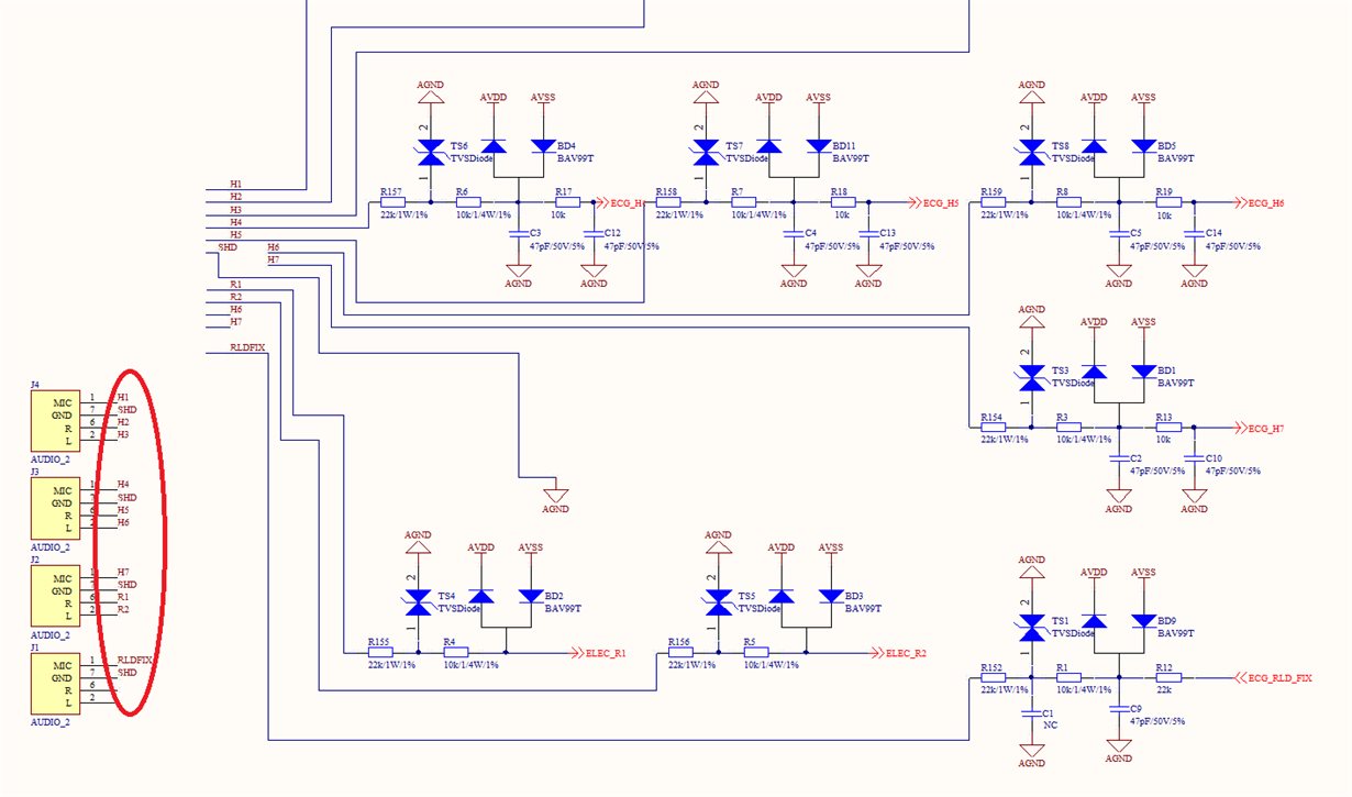
        My board: 


        All of the pins in the red circle except RLDFIX are connected to SHD, while SHD is connected to AGND.

        ADS1298RECG-FE:


        All of the pins in the red circle except ELEC_RL are connected to SHD, while ELEC_SHD is connected to AGND.

        Internal Shorted: Not shorted on the PCB board. Both of the boards are shorted by setting CHnSET register MUXn[2:0] bits "001 = Input shorted".

        Thank you.

    Frank


  • Hello Frank,

    First, let me say that the numbers in the datasheet for input short noise are taken with an external short rather than an internal short since we want to show the noise of the entire signal chain inside the chip rather than just after the internal switches. However, the short is made very physically close to the ADC such that noise does not have much area to couple in before reaching the ADC.

    I will answer the questions from your last post:

    1. The RMS noise value that you achieved in test 2 is lower than we have seen in our tests. Are you sure nothing changed between the setups? Like a gain setting or reference voltage?
    2. Generally no. There should be thermal noise from the resistors as well as current noise generated by the diodes. The internal short method should produce the best results (or within measurement error thereof).
    3. Every input that could be exposed to a defib pulse will need to be protected. However, care must be taken not to make the impedance on the respiration electrodes too large because that will shrink the respiration signal. You can make R28 and R29 a little smaller if you need to make the protection resistors smaller.
    4. I'm not convinced that the diodes are causing the noise. One way to check is to remove the diodes and repeat the test. One thing that could cause noise on the channel 1 inputs is the fact that the inputs are shunted to AVDD and AVSS, both of which will have some 1/f noise that may couple in to the inputs and may not be exactly common-mode. Are you using the exact same power ICs for your board as the EVM?

    One thing I notices looking at your schematic and your picture is that you have a ribbon cable that extends from your board. Are the inputs shorted at the other end of that ribbon cable? If that's the case, that is a long wire for unwanted signals you couple on and make the noise larger. Does the noise get better when you short closer?

    Regards,

    Brian

  • Hi Brian,

        1. Yes, I'm sure the setup has never changed. And I tried another board, the result is the same.

        2. And I tried this:

            The inputs are all externally shorted on my board in the following Test1 and Test2.

            Test1: Set as "Normal electrode input".      Result: uVpp(uRMS)  =    2.14(0.32)

            Test2: Set as "Input shorted"                      Result  uVpp(uRMS)  =    3.71(0.58)

            No matter how many times repeated, the result is almost the same.

            Note that, in Test2, the inputs are both "Internal shorted" and "External shorted". But the noise is even larger that jut "External shorted".

            I think that cannot be explained!

        4. I remove the TS4\TS5\BD2\BD3 in the protection circuit of CH1 and change R155/R156/R4/R5 to 0Ohm. Which means the whole protection circuit for CH1 is removed.

            Now the lead circuits are exaclty the same with the EVM board.

            But the results does not change. The CH1 still has much bigger noise than other channels.

            I will try more tests to find.

         Thank you so much!

    Frank

  • Frank,

    Without being there, it's tough for me to say what could be causing the issues. The only advice I can offer is to try to remove things incrementally until the thing you remove causes it to work as expected. This could mean removing capacitors, replacing resistors with 0 Ohm, using a bench supply as the power supply for the board, etc. I look forward to seeing what you can find out!

    Regards,
    Brian Pisani