This thread has been locked.

If you have a related question, please click the "Ask a related question" button in the top right corner. The newly created question will be automatically linked to this question.

ADS 1262 too mach noise.

Other Parts Discussed in Thread: ADS1262

Dear Sir,


Question1,

      We just finish our PCB to test the ADS1262 performance. But the result is unsatisfactory. The Noise is about (200nV-300nV).

      The signal is made by a very stable current source and very low TRC standard resistance. (We use the 7 1/2 multimeter can measure mach less noise than obtain by 1262).

      Below is our parameter (reference LT1019A-3.3V; gain-8; chop on; filter sinc4; 2.5sps rates)

       WritRegis(REFMUX,REFAIN0_G);

WritRegis(MODE0,CHOP_ON);

WritRegis(MODE1,FILTER_SINC4);///*Sinc4 mode

    WritRegis(MODE2, GAIN_8| DR_2_5_SPS);//2.5sps

        WritRegis(INPMUX,MUXP_AIN2 | MUXN_AIN3); //


Can you give us some advice for this issue?


Question2,

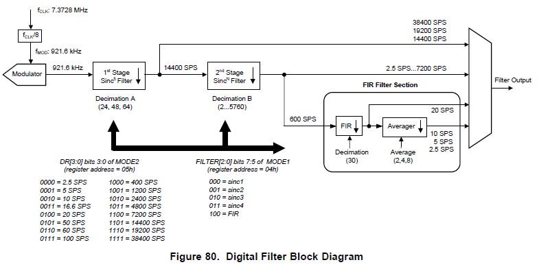
For ads1262 there are two stage filter first sinc5 and second stage variable-order filter.so the question is how to run the first stage filter, I don’t think is the reason of the importance noise.

thank you for your anwer.


Xavier-Pan


  • Hi Xavier,

    To answer your questions:

    1. Are you measuring the noise with respect to the PGA input (input-referred) or PGA output (output-referred), and are you using RMS or PP units?
      Depending on how you measure or describe the noise, 200-300 nV may not be bad performance...

      The ADS1262 datasheet provides the "input-referred" noise - this means the observed noise gets divided by the gain. It is more useful to discuss the "input-referred" noise since this equivalent to the smallest input signal that you can resolve - as if you have an equivalent noise source that was adding to your input signal. Therefore, with 2.5 SPS, SINC4 filter, chop ON, PGA = 8 V/V, you would expect to see about 13 nVrms x [1/ SQRT(2)] = 9 nVrms "input-referred" or 9 nVrms x 8 V/V = 75 nVrms "output-referred" (Note: the [1/ SQRT(2)] factor is to account for the noise improvement due to chopping).

      Next keep in mind that RMS and PP (peak-to-peak) noise may vary for a few reasons. If the noise is truly random (or Gaussian), you'd expect the PP noise to be about 6x the RMS (standard deviation) noise. So you're likely to see 9 nVrms x 6 c.f. = 56 nVpp "input-referred" or 56 nVpp x 8 V/V = 450 nVpp "output-referred". Additionally, if your noise is not Gaussian, say for example that your input signal drifts due to a change in current or resistance, then the RMS and PP noise will increase significantly due to a changing DC average. If you would be able to share the raw ADC data, I could take a look at it and see if the noise is really due to random variations in the output result or if the DC average was drifting.

      It may also be a good idea to try measuring the noise with the ADC inputs shorted to ensure that the noise is not coming from your input signal. This should also provide a result that is more closely matched to the data sheet specifications.


    2. The first stage digital filter is in series with the second stage. For most data rates, you'll get the combined filtering effect of the first and second SINC filter stages. However, if you want to get the data directly from the first stage, then you'd need to select a data rate of 14.4, 19.2 or 38.4 kSPS. 


      NOTE: The noise performance will be not scale linearly with the bandwidth when using these faster data rates, as you'll start to see more of the modulator's high-frequency noise above several kHz:


    Please let me know if that information answered your questions, or if you have any additional questions I can help with!

    Best Regards,
    Chris

  • Dear Chris,

    1)       Thank you for your answer, so here is the measure data raw(unit V). (I think is random noise) what is your advice (algorithm or other solution)

               2) Which means ads1262’s PGA give result so much noise, and how to reach the close to 24BIT ENOB, because we use another 24BIT ADC can do 22.5bit ENOB and less noise than 1262.(We use same basic circuit).but the resolution is not Enough. Possibly you have some advice to modify our hardware or you can check our test Source Code. (I can send to your E-mail).

    thank you

    best regards

    XAVIER-pan


  • Hi Xavier,

    I'm assuming that that is the output-referred noise (i.e. you don't divide by the gain). Even so, that is much higher than the ADC's characterized noise performance.

    Have you tried measuring the noise with the ADC's inputs shorted?
    This will give you a better idea of how much noise is coming from the ADC, since shorted inputs will not be affected as much from external noise sources (external signals or even the reference voltage).

    Feel free to send a schematic and any other information you would like me to review to pa_deltasigma_apps@ti.com.

    Best Regards,
    Chris

  • Dear Chris,

            We just test short the input, is same noise level. I just send the schematic in your E-mail. Please give us some advice.


    Best Regards,
    Chris

  • Dear Chris,

                    We update our schematic and send to your E-mail. and I think we find the source of noise that is our USB port. Just unplug the USB port  that's all.  

    BR

    XAVIER-pan

  • Hi Chris,

    I have the same problem. I used ADS1262 to measure a signal, which was configured with 10Hz, 10mV, sine ware, from a function generator. The measured data was shown as attached. 

    The configuration of ADS1262 is as follows,

    SPI clock : 16MHz

    Sample rate : 4800 SPS

    Filter : Sinc1

    Reference : Internal reference.

    (Y-axis in mV)

    Do you know how to fix this issue? Thank you.

    XView

  • Hi Sunglin,

    I'd be a bit concerned by the SPI clock frequency you listed...the master clock ("CLKIN")  and SPI clock ("SCLK") should not exceed 8 MHz. 

    Going outside of this range may be the reason for the degraded noise performance.

    Additionally, I always recommend that you first test the ADC's noise performance with the inputs shorted! Testing the noise in this way removes the input and reference noise, and allows you to compare the noise performance to the noise specifications (Table 1 in the ADS1262 datasheet). With a 32-bit ADC, you will certainly be able to see all of the noise coming from your signal generator!

    Best Regards,
    Chris

  • Hi Chris,

    You are right.  I've checked the signal by using oscilloscope, the signal wave is same as ADS1262 measured. So it's not the problem of ADS1262. Thank you.

    But now, I've found a new issue when I used ADS1262 to measure strain gauge. The measured data is drifted, which was shown as attached figure. I left everything on the table and the measured signal drifted up and down.  

    The unit of Y-axis is mV.

    Thank you.

    XView.

  • Hi Sunglin,

    Would you be able to share a schematic of your circuit (you can send it to me at pa_deltasigma_apps@ti.com)?


    Suggestions:

    I would first check your reference voltage to make sure that it is stable.

    I would also recommend to use the strain gauge's excitation voltage as the ADC's reference voltage. Doing this creates a "ratiometic" measurement that is less sensitive to changes in the reference voltage. Often times this will significantly improve the measurement drift.

    Additionally, you may consider enabling the ADC's chop mode to significantly reduce the ADC's offset and offset drift.

    To further improve the drift performance, you might consider implementing chopping at the sensor (aka. "AC excitation"). There is a reference design that explins this technique in more detail here:  

    Best Regards,
    Chris