This thread has been locked.

If you have a related question, please click the "Ask a related question" button in the top right corner. The newly created question will be automatically linked to this question.

DAC8760: mA output stops working, Voltage output continues to work

Part Number: DAC8760

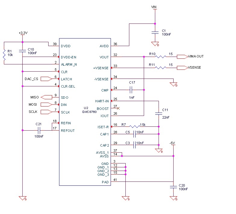
We are developing a product that uses this chip, and have the V and mA outputs tied together.  We did not enable the DUAL OUTEN bit, as per the warning in the app note.  The issue is, both the voltage and current outputs work fine for a few days, but then the mA output can only go up to 0.930 mA, for no apparent reason.  This is the second prototype board of ours that has this problem.  On the last board, I ran a test overnight with the output set for 20 mA.  When I returned this morning, it was still outputting 20 mA.  I removed power, removed the PC board from our enclosure, then powered it back up again.  The output would only go to 0.973.

Here is our initialization code:

v_DAC8760_Write(DAC8760_WRITE_RESET, 1);

v_DAC8760_Write(DAC8760_WRITE_CONTROL, CLRSEL);

Later in the code when the output type/range is selected, this is what we do:

v_DAC8760_Write(DAC8760_WRITE_CONTROL, (u16_Range | OUTEN | REXT | OVR));

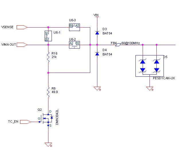
We are using a MAX14777 quad analog switch (U6), so that we can switch VSENSE in such a way that we can also provide a thermocouple output as well as Voltage and Current outputs, without having errors due to the switch on resistance. 

Again, everything works fine for a few days, then suddenly, the mA output malfunctions.  With the DAC count set to 0xFFFF, the output is 0.930 mA.  With the DAC count set to 0x0000, the output is 0.915 mA.  Here is a part of our schematic,  I can't include everything because of confidentiality and company policy.


  • Albert,

    I apologize for the late response - things are off to a hectic pace this year and this post slipped past my attention.

    Schematically I do not see any issues with your circuit around the DAC8760. I would be interested in knowing more about what is going on with the U6 switches during power-up / power-down and what the state of the DAC8760 is during power-down (i.e. is IOUT still enabled and set to full-scale?). Similar questions for what is happening with Q2 during this sequence.

    What could also be helpful is an oscilloscope capture basically of what happens at the VOUT/IOUT terminal at power-down since power-off appears to be what creates the issue. Also seeing oscilloscope captures of the power supply lines AVDD and AVSS at power up and power down would be helpful.

    As a final layer of defense you could submit some of these, what sound to be damaged, units to us for failure analysis to see if that can give us any further clues as to what is causing this issue.
  • Kevin,

    I too, am sorry for the delay, and am busy myself.  I solved the problem on 1/18/2017.  I didn't capture any scope traces, but I am replying so that TI and other customers can benefit from my findings.  If you would still like scope traces, I can re-do the tests, but not anytime soon.

    Here is an excerpt from an email sent to my manager and our engineering group:

    All:
    I finally found the “smoking gun” that caused the DAC chip to be damaged.  With a 2.5 Ohm load connected, the very first time after power-up that the range is changed to mA and the output is enabled, there is an 80 mA glitch that lasts about 1 ms.  This was observed with an oscilloscope attached across the shunt (milliammeter) and measuring 200 mV.  However, every time thereafter that the output range is changed and the output is disabled and enabled, the glitch was not present – only on the first enable after power-up.  Also observed was that the DAC8760 does have the “smarts” to do a break before make when changing ranges and enabling the output.  Not only does it do that, but it keeps the output off for about 30 ms before enabling it.  However on the first range change/enable after power-up, it only waits 5 ms, and produces the high current glitch.
     
    The above tests were done using a 20 V power supply.  The unit that died Monday morning was powered by 24 V.
     
    To solve the problem, the firmware now does the following in all cases, whether it’s the first enable or subsequent enables:

    1.       Disable output

    2.       Select desired V/mA range

    3.       Wait 2 milliseconds

    4.       Enable the output.

     
    With this approach there is never a glitch.  You could say to use a higher resistance load, but you never know what the customer is going to hook up to it.  Also, we always calibrate our mA outputs (for everything) with the output connected directly to the milliammeter (2.5 Ohm shunt).
     
    Regards,
    Albert

    Thanks,

    Albert

  • Albert,

    I am glad you were able to resolve your issues, and thank you very much for posting the details of your solution to the forum for the community.

    Please let us know if you need anything else.