This thread has been locked.

If you have a related question, please click the "Ask a related question" button in the top right corner. The newly created question will be automatically linked to this question.

ADS1243: ADS1243 - how to read all channels in continuous mode?

Part Number: ADS1243
Other Parts Discussed in Thread: ADS1220, ADS1248

Hello,

I would like to ask you for best approach how to read all channels of ADS1243 in continuous mode (in my case I would like to read all 4 differential channels avaiable on ADS1243 continuously).

In MUX (01h) register I can select positive and negative pin for my differential channel (ADiff0). E.g. with defaults I'll have Ain0 as positive input and Ain1 as negative input (all other registers all set to default values). Then I can start RDATAC with 03h SPI cmd and I'll get ADC values of my ADiff0.

Is there any possibility to send data from all (normal/differential) channels continuously?

Or do I have to update MUX register with proper (diff.) channel settings all the time ( switching among Adiff0 = [Ain0;Ain1] ;Adiff1 = [Ain2;Ain3] ;Adiff2 = [Ain4;Ain5] ;Adiff3 = [Ain6;Ain7]). Is it possible to do it during continuous mode or it's nonsense and I should do it all on my own (set proper MUX cfg and then send "normal" RDATA cmd, etc.)
BTW.. I couldn't find Linux driver for this ADC. Do you know if it exists?

Thanks!

  • Ondrej,


    There no direct way of reading all channels continuously. As you mentioned, you would have to send a series of commands for each change in the channel and read of the device.

    Basically this is the sequence that you would need to run:
    Set the multiplexer to the proper input
    Send a DSYNC command to restart the digital filter and start a conversion
    Wait for a /DRDY to indicate that the conversion has completed
    Read the data
    Set the mux to the new input and repeat the sequence

    During this time the modulator is free-running and restarts each time the DSYNC command is issued. Ideally, the /DRDY triggers an interrupt to read back data. If the master delays the read, and a new /DRDY is issued during the read of data, then the data can be corrupted as the data output register is updated while the device is still receiving SCLKs.

    Sorry, but I don't know of any drivers written for this device. I did a quick search but came up empty.


    Joseph Wu
  • Hi Joseph,

    thanks for you reply!

    May I have additional question(s)?

    If I want to read "one shot" ADC value, I'll send RDATA command. I tought that then conversion is started immediately after cmd is received,  /DRDY goes HIGH and when conversion is finished /DRDY goes (active) LOW?

    /DRDY signal is generated on frequncy of sample rate even if I'm not using continuous mode?

    Thanks, Ondrej.

  • Ondrej,

    It helps to think that the ADC is continuously converting, even if you want to read a single value. To do this, you would set the registers to the desired inputs and configuration and then start a new conversion with a SYNC command.

    After the conversion completes, /DRDY transitions low to indicate that the conversion is completed. If /DRDY is already low, it transitions high for 4 tosc clocks before going low to indicate the conversion completion.

    After that, the ADC continues conversions, and will even if you decide not to read back the data. That's why you would continue seeing the /DRDY pulses. The ADC doesn't stop unless you send it a SLEEP command.

    Joseph Wu

  • Hi Joseph,

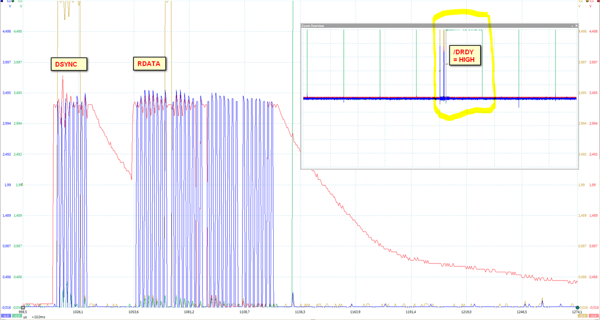
    I tried to setup pinmux, send DSYNC cmd and then immediately read converted data (I didn't wait for /DRDY low, because I want you to show that then /DRDY goes HIGH for long time.. should it be like this?).

    I tried to setup pinmux, send DSYNC cmd without reading, but I didn't get /DRDY pulse. /DRDY stays low from this moment.

    Am I doing something totally wrong?

    Thanks, Ondrej

  • Ondrej,


    I believe this is correct for the operation for the commands you've given, but I understand the confusion. I'll explain what's happening with the device.

    The /DRDY pin returns high at the completion of data read. It is discussed on page 14 of the ADS1243 datasheet. In the first figure you provided, that is what it is doing. Once you give the read data, it is simply giving you the data from the last conversion of the ADC. That data comes from the conversion indicated from the the /DRDY given just before the SYNC command. Once the DSYNC command is received, it starts the conversion, the RDATA command returns /DRDY high, and /DRDY returns low once that conversion completes. After that the ADC continues to convert.

    The second figure shows that the DSYNC command has not completed. The problem is that DSYNC requires more input to complete. If you look at DSYNC OPERATION (also on page 14 of the datasheet, you would first issue the DSYNC command. However, the ADC is held in RESET until the next rising edge of SCLK is given. It should have been explained better in the command section, but using the next rising edge of SCLK allows for a better exact timing of then the DSYNC occurs.

    Hopefully, that clears up any issues you have in operation. If you have any questions let me know.


    Joseph Wu
  • Hello Joseph,

    again, thanks for answers!

    I'm still little bit confused, because in post above you recommended me to do this:

    Basically this is the sequence that you would need to run:

    1. Set the multiplexer to the proper input
    2. Send a DSYNC command to restart the digital filter and start a conversion
    3. Wait for a /DRDY to indicate that the conversion has completed
    4. Read the data
    5. Set the mux to the new input and repeat the sequence

    I set up proper input in MUX (1), send the DSYNC (2) and then I would expect /DRDY that will inform me that I can read actual ADC data (3). (This shows my second figure from last post, but you said that I have to provide "next rising edge of SCLK".)

    In my first figure in last post this "next rising edge of SCLK" is provided from RDATA cmd. As a response on this command I got "wrong" - last converted value from previous pinmux. I know that you mentioned that "data comes from the conversion indicated from the the /DRDY given just before the SYNC command", but my intension is to setup MUX=diffch1 and read actual diff channel 1 data, setup MUX=diffch2 and read actual diff channel 2 data, ... 3, ... 4 and again. 

    I was curious and I tried to send DSYNC cmd followed by READ REG cmd (to provide "next rising edge of SCLK" ), but the conversion wasn't started.. Why?

    So still my question is how the cmd sequence should look like to have possibility read all diff channels continuously?

    Like this loop? What should be step 3?

    1. Set the multiplexer to the proper input
    2. Send a DSYNC command to restart the digital filter and start a conversion
    3. Send ???? command (providing "next rising edge of SCLK")
    4. Wait for a /DRDY to indicate that the conversion has completed
    5. Read the data

    In ADS1243 datasheet on page 10 is also written that:

    "In order to minimize the settling error, synchronize MUX changes to the conversion beginning, which is indicated by the falling edge of DRDY. In other words, issuing a MUX change through the WREG command immediately after DRDY goes LOW minimizes the settling error."

    I'm confused with statement "to the conversion beginning, which is indicated by the falling edge of DRDY".

    It means that loop should like this or am I missing something?

    1. Send a DSYNC command to restart the digital filter and start a conversion
    2. Send ???? command (providing "next rising edge of SCLK")
    3. Wait for a /DRDY to indicate that the conversion has completed (falling edge of /DRDY, right?)
    4. Set the multiplexer to the proper input
    5. Read the data

    Thanks Joseph, I have prepared basic Linux driver for this ADC, but I'm not able to read data properly in "all four diff channels continuous mode".

  • Ondrej,


    I'm sorry if I wasn't clear. Sending the DSYNC command will require an extra write to the device to start the conversion since the actual conversion is started on the next rising edge of the SCLK. So what you would need to do would be send

    1. Set the multiplexer to the proper input
    2. Send a DSYNC command to restart the digital filter and start a conversion
    3. Send a command to initiate the conversion (see below)
    4 Wait for a /DRDY to indicate that the conversion has completed
    5. Read the data
    6. Set the MUX to the new input and repeat the sequence

    For step 3 (send a command to initiate the conversion), I suspect that you could issue a dummy command such as writing 00h to the device, which would be the same as an incomplete read operation. This should start the conversion. You mentioned that you used a RREG command after the DSYNC and the conversion was not started. Normally, I would have expected that to work and I'm sure I've seen others use that to start the conversion for a DSYNC. I'm not sure what is wrong with your setup for that. Can you grab an oscilloscope shot of that transaction? It might be best to use an logic analyzer so that we can read the bit transactions.

    As for the comment on page 10 about minimizing the error and synchronizing the MUX change, this was meant to address what happens when you change channels, but do not run a DSYNC command.

    Here is an example: the device is in the middle of a conversion and you change the channel in the middle of the conversion without the DSYNC command. The conversion that comes out will be a combination of the measurement of the two channels. With this type of ADC, the output is similar to a running average (or really a weighted average) of the input during the conversion period.

    If you could synchronize the MUX change so that it occurs right after the DRDY, then there is a minimal amount of time that the ADC looks at the previous channel for the next read. Often, the data periods are long for the ADS1243. If you're running at 7.5SPS, then the data period is 133ms. If you are able to change the channel within 20us of the /DRDY, then the error that you will see from looking at the previous channel will be moderately small.

    If you use the DSYNC you don't have to worry about this. If you change the channel and then run the DSYNC, you restart the conversion. During that data period, the ADC would only see one channel.

    I would also note that many of our newer devices are easier to use. When the MUX changes in devices like the ADS1220, ADS1248, and ADS124S0x, the conversion restarts automatically, without the need for the DSYNC command. However, if you do need to make synchronize a conversion for other reasons, you are still able to do so.


    Joseph Wu
  • Hi Joseph,

    unfortunatelly I don't have a log. analyzer at the moment..

    I made oscilloscope screenshots again.

    In first figure I do steps 1, 2, 3 (dummy RDATA cmd), 4, 5 (real RDATA cmd => use this ADC value) and loop it.

    So after step 3 (dummy RDATA cmd) /DRDY goes high and I'm able to wait for end of conversion (indicated by /DRDY low) and in step 5 read my value.

    Why is /DRDY high after RDATA cmd whole conversion cycle?

    In second figure I do steps 1, 2, 3 (dummy READ REG cmd).. then conversion can run (I don't know?).. I'm expecting /DRDY high!? But 67ms after dummy READ REG cmd (I have default 15 Hz sample rate), /DRDY high pulse come. This is how it should be?

    Next figure is detailed DSYNC and dummy READ REG cmd.

    Thanks Joseph

  • Ondrej,


    I'll go through the plots in the order that you show them in the last post.

    In the first plot. It looks like it does exactly whaht you program it to do. You issue the DSYNC, and then run a dummy RDATA, which raises /DRDY in response.

    In the second plot, you use the RREG after the DSYNC to start the conversion. The conversion you see from the /DRDY is valid. You can see based on the time spacing that the conversion has started after the RREG command.

    I know that you were expecting /DRDY to go high after the RREG, but isn't the case. The datasheet states that the /DRDY returns high after when a read operation from the data register is complete. Apparently this is only for the data output register (DOR) and you would only get this with the RDATA command.

    In the last plot, you have a closeup of the DSYNC and RREG command, but as I mentioned, it won't return the /DRDY high.

    Normally, I recommend that the /DRDY trigger an interrupt to start the collection of data. However, if you are polling the /DRDY, I can see why you would want to return /DRDY high. In that case, just use the dummy RDATA command to do so.


    Joseph Wu
  • Hello Joseph,

    sorry for my late response.

    I was thinking about the second plot and your explanation -> ".. you use the RREG after the DSYNC to start the conversion. The conversion you see from the /DRDY is valid."


    As I said before, I'm trying to read all 4 differential channels (setup on ADS1243) sequentialy by polling. I send MUX cmd for next channel, then send  DSYNC to start new conversion and RREG. Then if I'll read the value immediately (you are saying above that the value is valid), I'll get value for previous channel, because the conversion wasn't done yet for my last change MUX cmd, right? Or you mean that after RREG I should wait for /DRDY raises high and then /DRDY goes active low again (and than read "valid" data)?

    (BTW: ADS1243 is not normally used to read from all channels sequentialy?)

    Best regards, Ondrej

  • Ondrej,


    Sorry, but I was out of the office for most of last week.

    If you send send the MUX command for the next channel and then send the DSYNC (and then the RREG for the SCLK), you'll start the new conversion. Once you start the the conversion the ADC needs an entire data period to collect the samples from the input to get a conversion. If you run at 7.5SPS, the data will be good after 133ms.

    You are correct in that if you read data immediately after starting the DSYNC, you will get the data for the previous channel. If you want, you could start by setting the channel, send the DSYNC command, and then use the read of the previous channel to initiate the new conversion. You would just need to make sure that you perform the read before the conversion completes for the new channel if you want to capture the previous channel.

    I know that this interface is a involved for reading sequential channels, but it does work.


    Joseph Wu