This thread has been locked.

If you have a related question, please click the "Ask a related question" button in the top right corner. The newly created question will be automatically linked to this question.

ADS1298R: How to make the defibrillator protection circuits for the respiration inputs of ADS1298R?

Other Parts Discussed in Thread: ADS1298R

Hi TI experts,

      I've looked through all the posts on defibrillator protection circuits in the forum.

      The SPARB36B.pdf and https://e2e.ti.com/support/data_converters/precision_data_converters/f/73/p/176956/882080#882080 give me good reference.

      But for the respiration circuits of ADS1298R, what is the suggested defibrillator protection circuits?

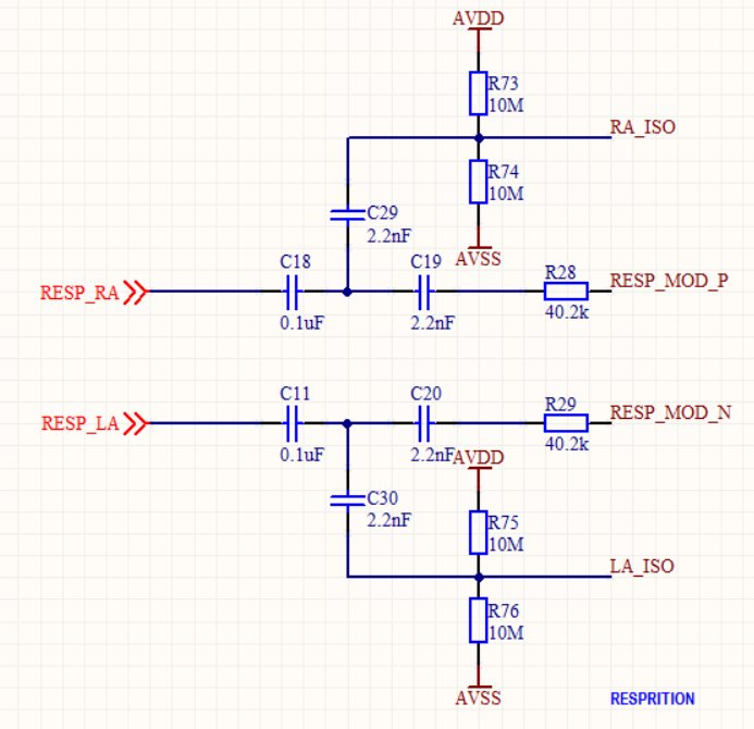
      What defibrillator protection circuits should I take before RESP_RA and RESP_LA in the following circuits?


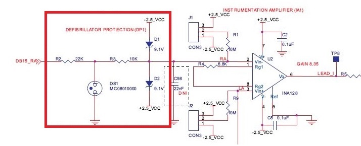
    I tried the circuits in red frame in the following schematic. But the respiration signal can not be got, because the R2+R3 is too big, which attenuates the respiration signal (I've read the sbaa181.pdf).

    I changed R2=1k and R3=0, the respiration signal can be got. But that 1k+0 is too small for defibrillator protection.


     What is the correct way to do defibrillaotr protection for the respiration circuit?

     Thank you so much!

Frank

  • Hey Frank,

    Essentially you will want to protect all of the inputs separately. Recall that if the resistors are outside the "loop" formed by the RESP_MODP/N pins and the patient, they will not affect the current magnitude that flows there. Therefore you could put protection on the input path before C30 and C29 (nothing that, of course, you will need to protect the capacitors from high voltage).

    The RESP_MODP/N pins already conveniently have 20kOhm resistors on them. You may have to switch the order between the resistors and capacitors to protect the capacitors, but you can use those resistors as current limiters in the event of a large voltage transient. Remember the impedance of two series elements does not change with the order they are in. You may also increase the resistance of R28 and R29 noting that the current that flows in the "loop" will be slightly less.

    C18 and C11 may not be absolutely necessary either so you can avoid worrying about blowing up those capacitors.

    Brian
  • Hi Brian,

           Thank you very much for reply!


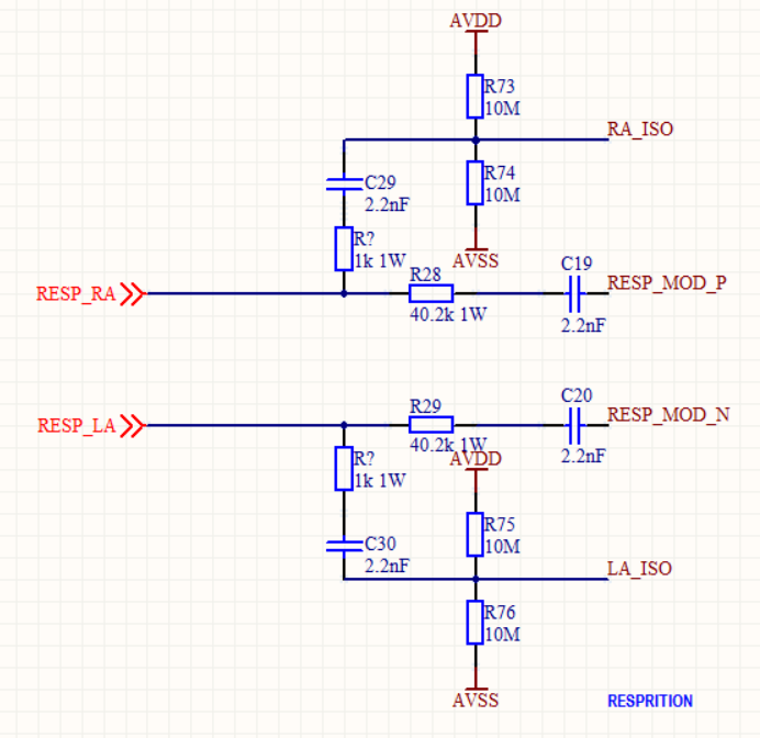
           Follow your suggestion, I modified the schematic as shown above.

           Q1. Do I understand right?

                 1. I take 2 R? (1k 1W) before C29 and C30.

                 2. And the order of R28 and C19 is changed, and I also change R28 to 1W.

                 3. C11 and C18 are removed.

           Q2. Is TVS or neon needed?

           Q3. I find in SBAA181.pdf, it says that "Capacitors C11 and C18 serve as a secondary means to prevent a single fault (for example, a shorted

    C19 capacitor from a carrier generator) from causing excessive dc currents through the patient."

                 Is there any way to keep C11 and C18 (for secondary means to prevent a single fault) while having the protection?

           Thank you.

    Frank


  • Frank,

    1. You may want more than 1 kOhm depending on how much current you expect to be able to sink in your supplies.
    2. Yes you will need some kind of protection device shunting to both supplies immediately behind both R?s, R28 and R29.
    3. You can only keep think if they are rated to withstand the defib voltage.

    Brian
  • Hello Frank

    To answer your question about defib protection on the respiration inputs,

    Remember that the ECG and Resp inputs both share the connection to the patient electrode inputs.

    So if you add a high voltage clamp right at the patient electrode inputs, you will protect the ECG and the Resp circuits.

    The best way to show you is using the schematic for the TI development board as a reference.

    You can download the ADS1298R development board users manual from the TI website,

    On page 1 of the development board schematic, J1 is connected to the Patient Electrode wires.

    At each input of J1, add a 1Kohm 1Watt resistor in series with the patient electrode wire.

    Now on the board add a SMBJ14 bidirectional diode from each input pin of J1 to ground.

    (Using Bidirectional diodes to protect in both discharge polarities.)

    The SMBJ14 diodes will limit the input voltage at the board to about 25V, and the 1Kohm resistors withstand the defib energy.

    (I have found that large carbon comp resistors work the best.)

    These 2 parts added to each input will protect the entire board from any input voltage going above or below 25V.

    The existing input circuits on page 1 of the development board will then limit the input voltage more to protect the ADS1298R.

    I hope you find this information helpful and can apply the methods to your project.

    Bill Burris

  • Hi Bill Burris,

          Thank you so much for reply!

          I appreciate your answer and help very much!


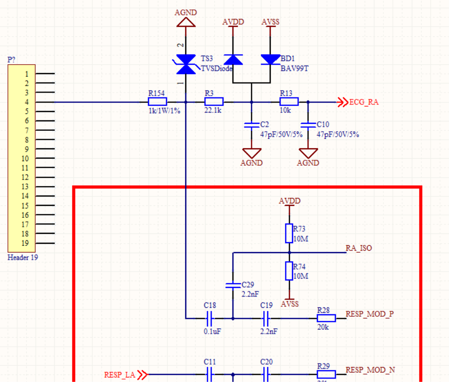
         Follow your suggestion, I made the above schematic (only RA is drawn).

         The R154 (1k1W) I use 2512 package.

         Q1. Do I understand right?

         Q2. For R3(22.1k), is 0402 1/16W sufficient?

         Q3. For R154, do you mean it should be made before the connector? It should be made in the wire? What's the difference if it is made on the PCB board?

         Q4. For R154, is 1k sufficient? Since in SPRAB36B.pdf it use a 22k.

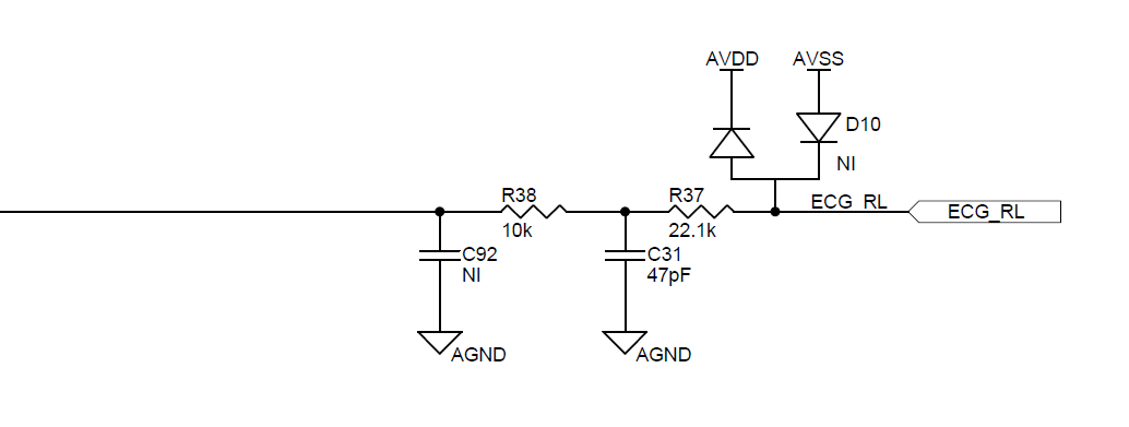
         Q5. For the ECG_RL, TI reference board put D10 after R37 (as shown below), but I think it should be put before R37. What's your opinion?

        Q6. For the ECG_RL, how much should C92 take? The TI board reference didn't give the value. 

        Thank you!

    Frank

  • Hello Frank!
    I can answer your first question; Yes, I think you get it, you are asking good questions.
    1. Yes, the schematic changes you made are almost correct. You need to add a BAT99T to the junction of C18 and C19 to protect the Resp circuits.
    2. When the defib 5KV discharge is applied there is a very short period of time before the SMBJ14 diode conducts. This transient high voltage spike can arch over a 401 resistor body. I suggest using at least a 0603 resistor and make the pads as far apart as possible to maximize the gap distance. In addition, C18 should be a 0603 100V part at minimum for the same reasons.
    3. The location of the 1K1W resistors must be before the connector, in the wire path. The 5KV defib discharge voltage will arch across the connector pins and shunt energy from the patient. If the 1K1W resistors are at the device end, the wire must withstand 5KV. If the 1K1w resistors are at the patient electrode connection the wires only have to withstand the 25V.
    4. The reason for using 1K1W resistors is to assure the device can never shunt more than 10% of the defib energy from the patient, every lead wire should have the 1K1W resistor added. The reason it is only 1Kohm and not higher is for respiration sensing. The resistors are in the patient impedance path, sensing a 1 ohm change in body impedance is challenging with the 1Kohm and would be impossible with higher resistance.
    5. For the RL connection I would suggest removing C92, C31, and R38. The SMBJ takes the place of C31, the 1K1W takes the place of R38. Resistor R37 should be the same as the other patient input resistors.
    6. C92 is not needed.

    And one more note;
    The defib energy is at 5KV and about 400 joules. The 1K1W resistors must be able to withstand 10% of that energy which is 5KV at about 40 joules. I would recommend Leaded Carbon Comp resistors, they are the only parts I found that work for this application. Check out Ohmite OX series.
    The SMBJ14 diodes can withstand the defib energy, but if you have room on the board, you may want the larger SMCJ14 instead to be safe.

    Exciting Engineering!
    Bill Burris
  • Hi Bill Burris,

          Thank you so much for the detailed suggestion! I have learned a lot from your answer.

          3. I think your explanation is quite reasonable, I got it.

              But I found the leads and wires I bought have no 1k1W protection resistor.

              And I didn't find any leads and wire with the protection resistor on the alibaba.com .

              Maybe make they made it on the PCB?

          4. Can I use 1k1W for RA and RL since they are also used for respiration detection, and use 22k1W for the other leads?

              Because 22k1W can have a smaller package and my PCB has limited size.

              I think, normally the leads should have the same resistor value, to have the biggest CMRR. But the electrode resistor maybe different for each lead since they are put on different parts of the body, and the value maybe change if the body moves. So I think keep the same value for the input resistors on PCB may be not necessary. What's your opinon?

          Thank you.

    Frank

  • Hello Frank

    Yes the resistors can be on the board as long as the ECG wires can withstand the 5KV.

    Where the wires attach to the board, make sure there is sufficient gap between the connectors and resistors for 5KV. (About 8mm between conductors)

    I would not suggest using different input resistor values, CMRR is VERY important in ECG monitoring.

    The body resistance does not change much on the patient between any of the leads. Body impedance is usually less than 100ohm.

    The issue with mismatched components on an ECG front end is phase delay differences at the inputs.

    So keep the components matched as much as possible.

    And I suggest testing the CMRR performance to make sure it is good.

    A good ECG design goal is -90db CMRR, and the absolute minimum performance must be -60db CMRR.

    (Keep in mind, a device that barely passes -60db usually does not work very well in real life.)

    To measure the CMRR performance of an ECG monitor, I apply a 1Vp-p sinewave directly to all input snap leads in reference with the RL snap lead.

    Then I slowly sweep the input frequency from 0.67Hz to 150Hz and assure there is never more than 1mV of signal on the ECG output display. (1V in and 1mV out is -60db)

    I know this test is different than the test described in IEC but if you can pass this test you shouldn't have any problem passing the IEC test.

    (This is how an EE should test ECG CMRR performance, just like it is a Diff-Amp.)

    Good luck with your design!

    Bill Burris

  • Hi Bill Burris,

          "About 8mm between conductors", Do you mean it should at least 8mm gap between the connector pins, and at least 8mm between the 1k1w resistors?

          Then the connector would be very large, at least 80mm long.

          Thank you.

    Frank

  • Dear Bill,

    Could you please take a look at this topic.

    i really need your help, it's related to the same topic of defibrillation protection

    e2e.ti.com/.../617771