Hello,
My group purchased eight DAC7744EB chips for our analog control boards.
Each board mounts two DAC7744 and has eight analog output channels. The power supplies for each board are +/- 15V and 5v.
Let's assign each chip's output as Channel 1~4
During the testing, I noticed that when I tried to set the voltage of Channel 3,4, the DAC analog outputs worked well from -10V to +10V except the range from 0 to around 0.5V
For example, my initial analog output was 9V, then I could set the output to 5V, 2.5V, 1V and 0.6V without any trouble, but when I set the output to any voltage between 0V to around 0.5V, the DAC didn't response to the command. Once I set the output to negative value from -0.1V to -10, the chip worked again.
Channel 1,2 don't have such issue. But the threshold problem exists in all eight chips.
Thanks in advance!
Updated: 2/21/2017
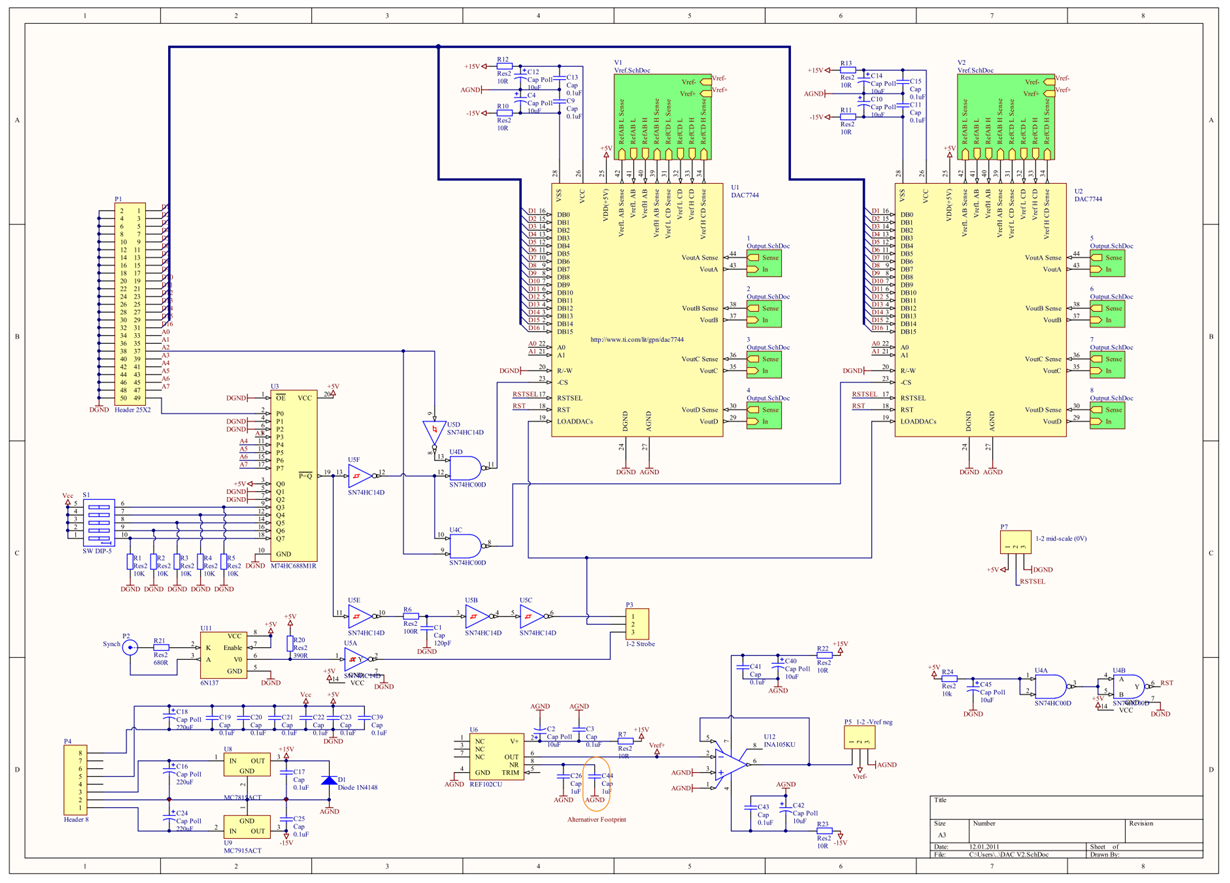
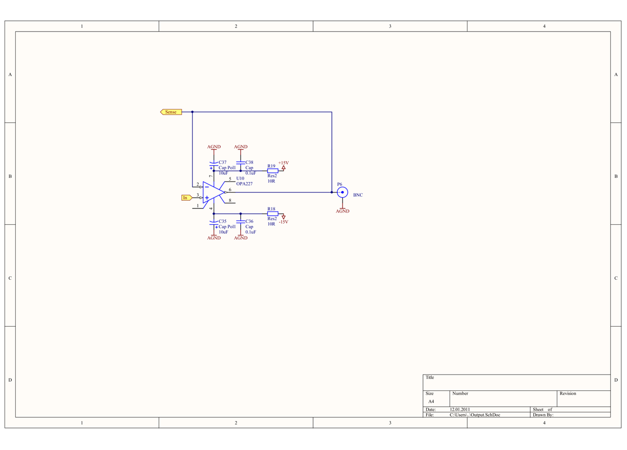
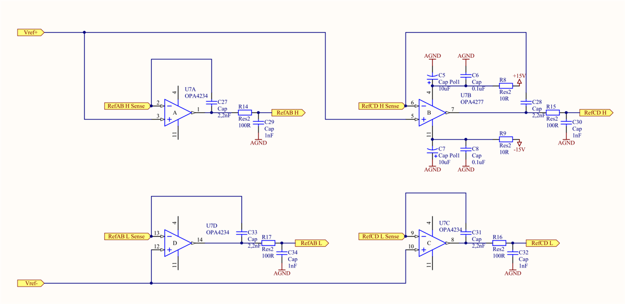
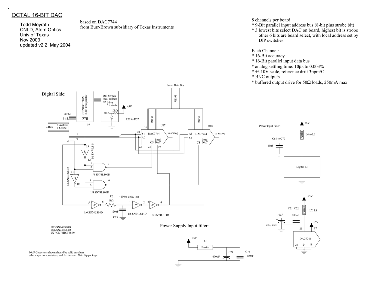
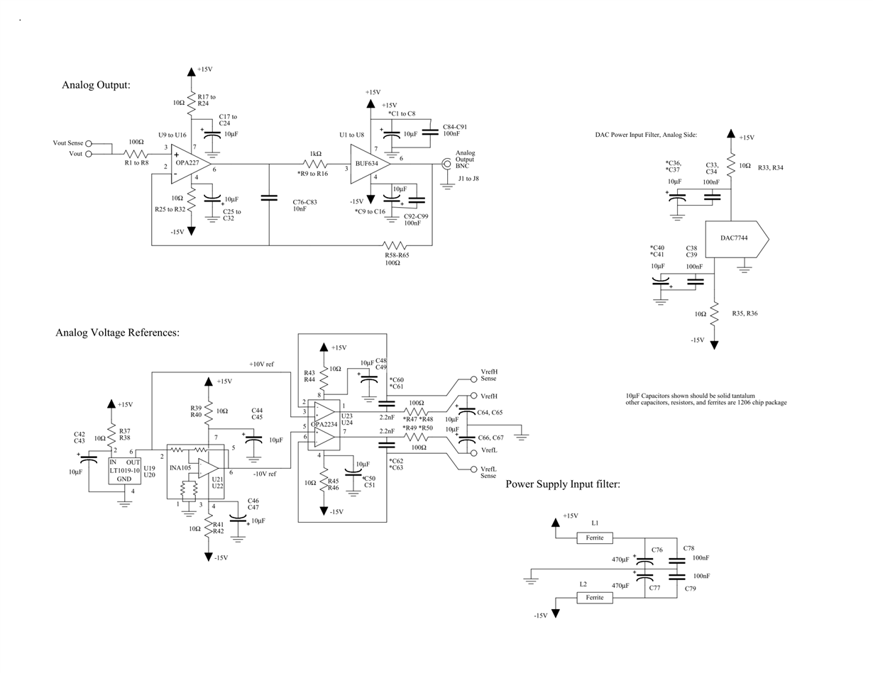
Here are the design schematics my group used. It is based on the designs from Atom Optics Laboratory Center for Nonlinear Dynamics and Department of Physics University of Texas at Austin. [http://www.strontiumbec.com/]
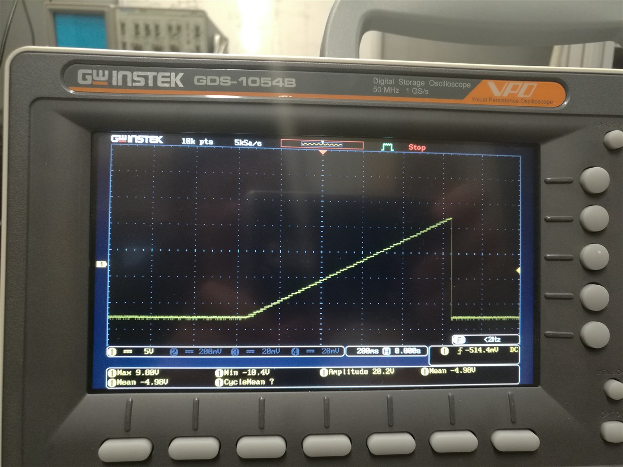
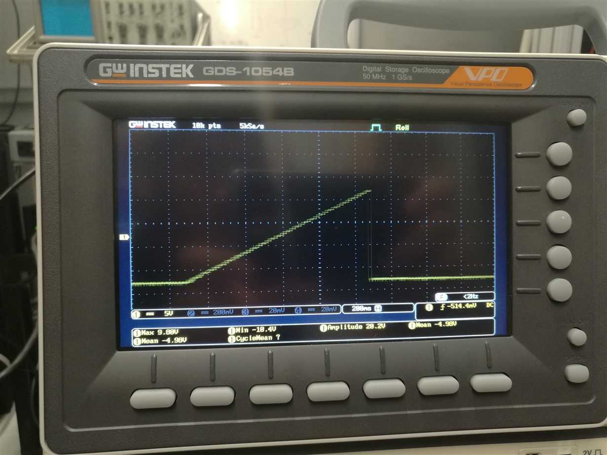
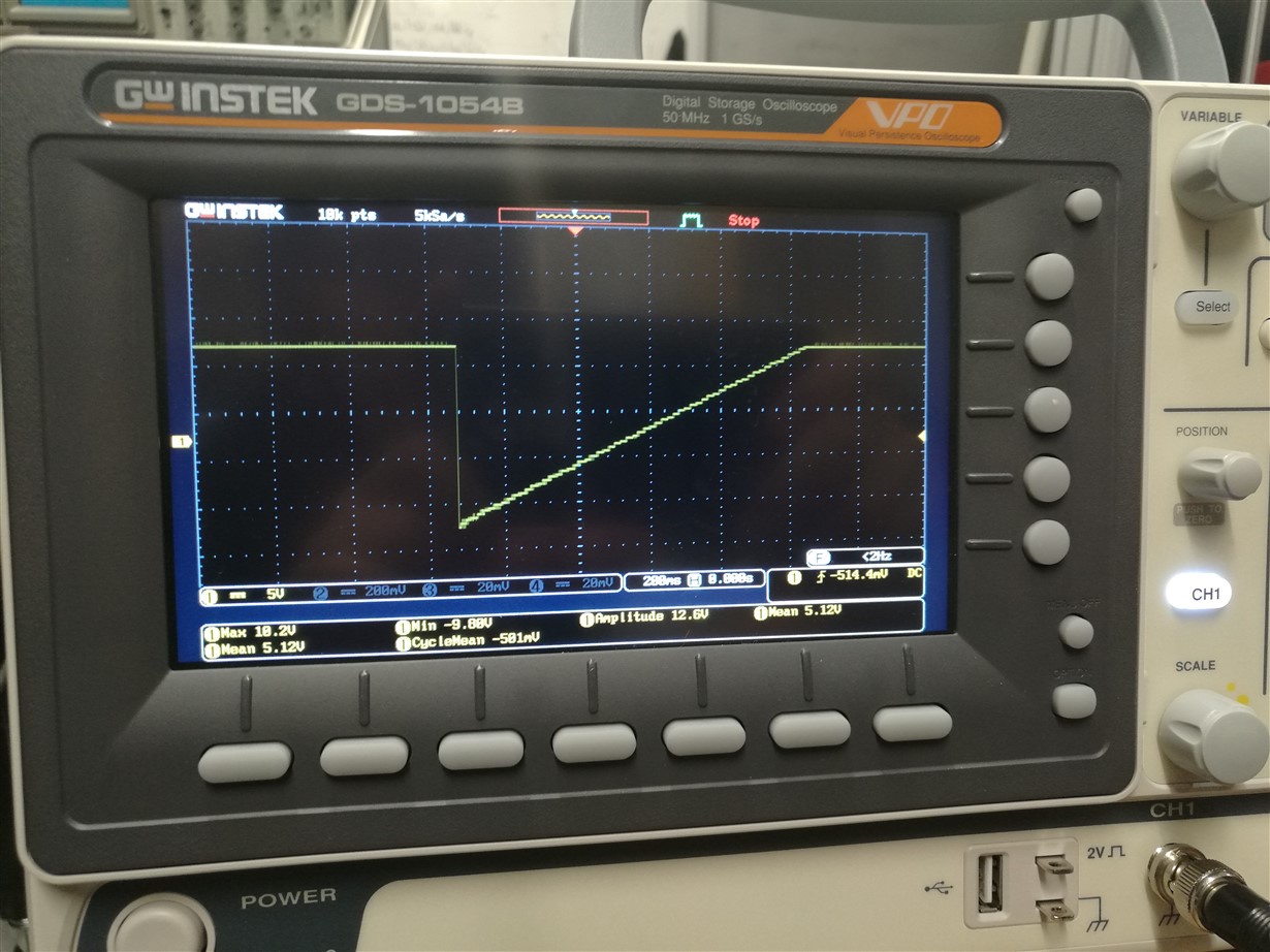
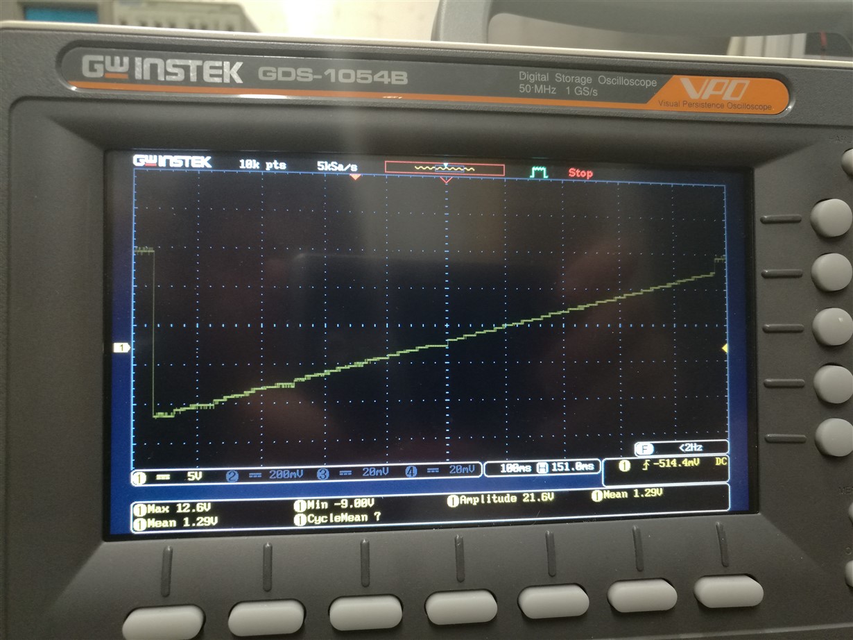
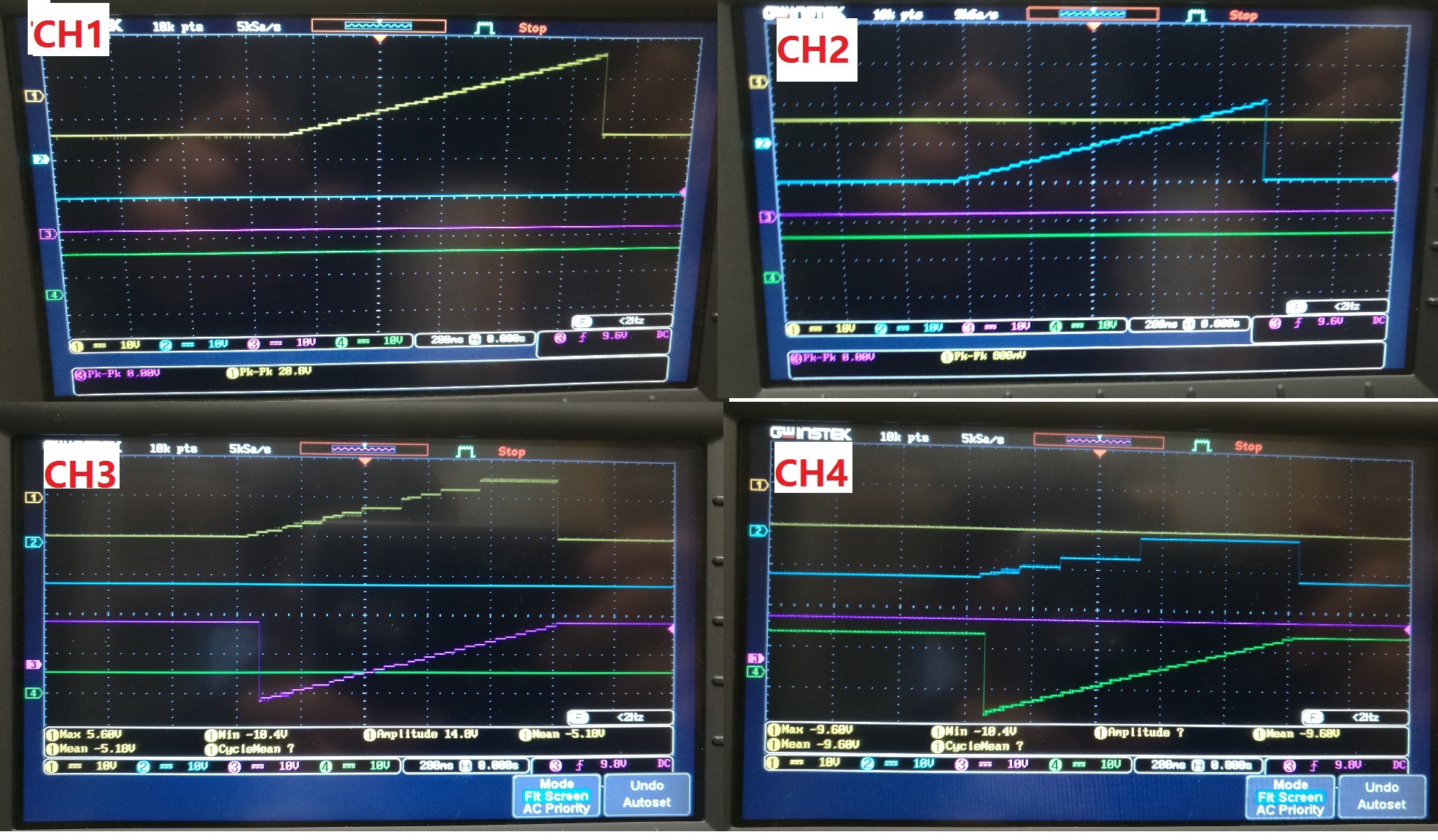
I did a fine ramp scanning test which started from -10V to +10V and then went back to -10V.
Here are the results:
So, channel 1 and 2 performed as expected. Channel 4 had decent ramp shape but did not reset back to -10V.
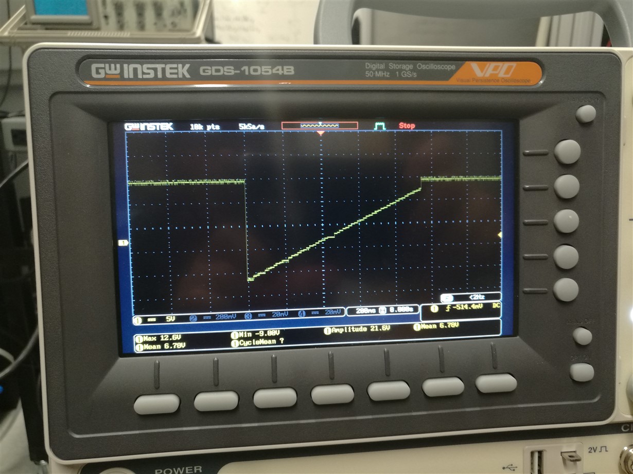
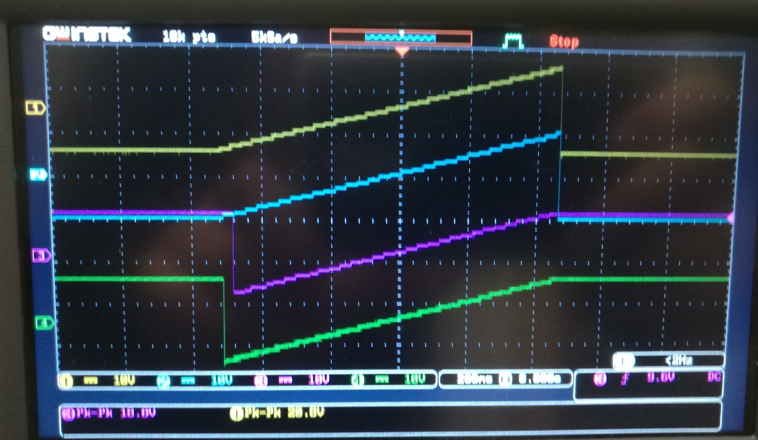
Channel 3 had the worst ramp shape. It was noisy and had a gap in the middle around 0 to 0.5V and it did not go back to -10V.
All eight chips I used had the same issue.
Channel 3 enlarged result:
The software part should be good, because channel 1 and 2 performed well. The output op amps should be good too, because I directly measured the outputs from the DAC7744 and noticed the outputs from DAC were wrong. Therefore, I suspected it should be the problem of the DAC7744 chip itself.
My group built another control system which used the same DAC7744 but different batch, and they performed well for all channels.
This problem really delayed my work, and I really appreciate your helps!
Updated: 02/23/2017
As Paul suggested, I connected 4 channels to the oscilloscope and found one of the problems which I didn’t notice. When I was scanning Channel 3,4, Channel 1,2 also generated a waveform. Based on that, the address bits did have some problems when they reached DAC chips.
I used a DMM measured the resistance from our controller to DAC7744 chips and found the resistance of is below 1 ohm for A0 and A1 signal traces.
Here I listed the results:
Channel 1: Yellow; Channel 2: Blue; Channel 3: purple; Channel 4: green.
Single channel scanning from -10V to +10V for channel 1,2,3,4:
Scanning two channels at the same time, Channel 1 and 2:
Scanning two channels at the same time, Channel 3 and 4:
Scanning four channels at the same time:
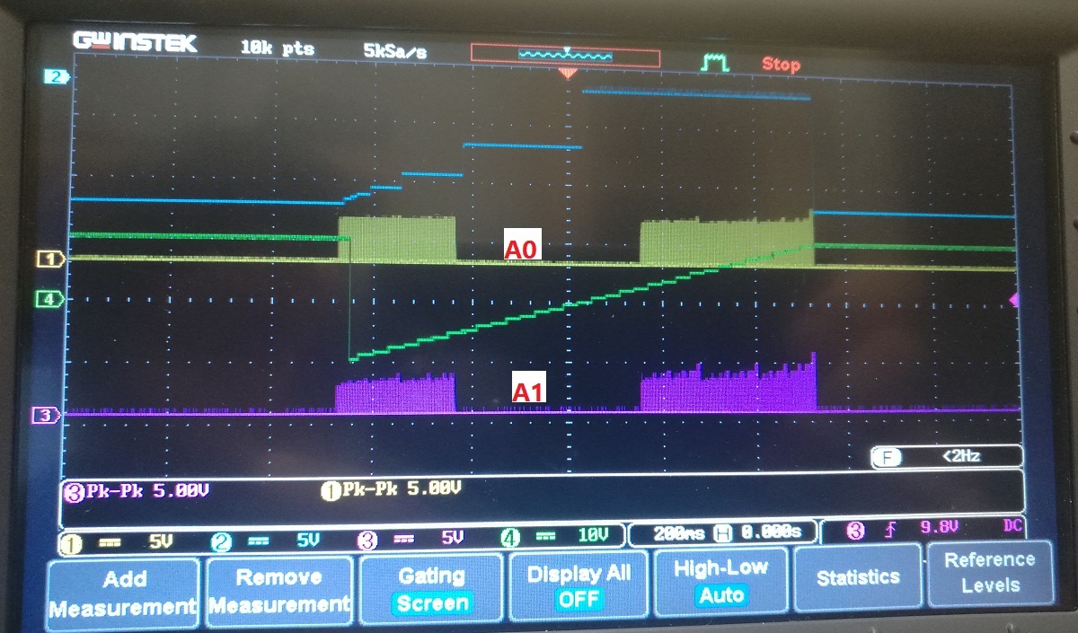
Scanning channel 4 with A0 and A1 signal, whereas A0 is yellow, A1 is purple:
Noticed that A0 and A1 signals were not square wave, and I was wondering if that could be the problem. 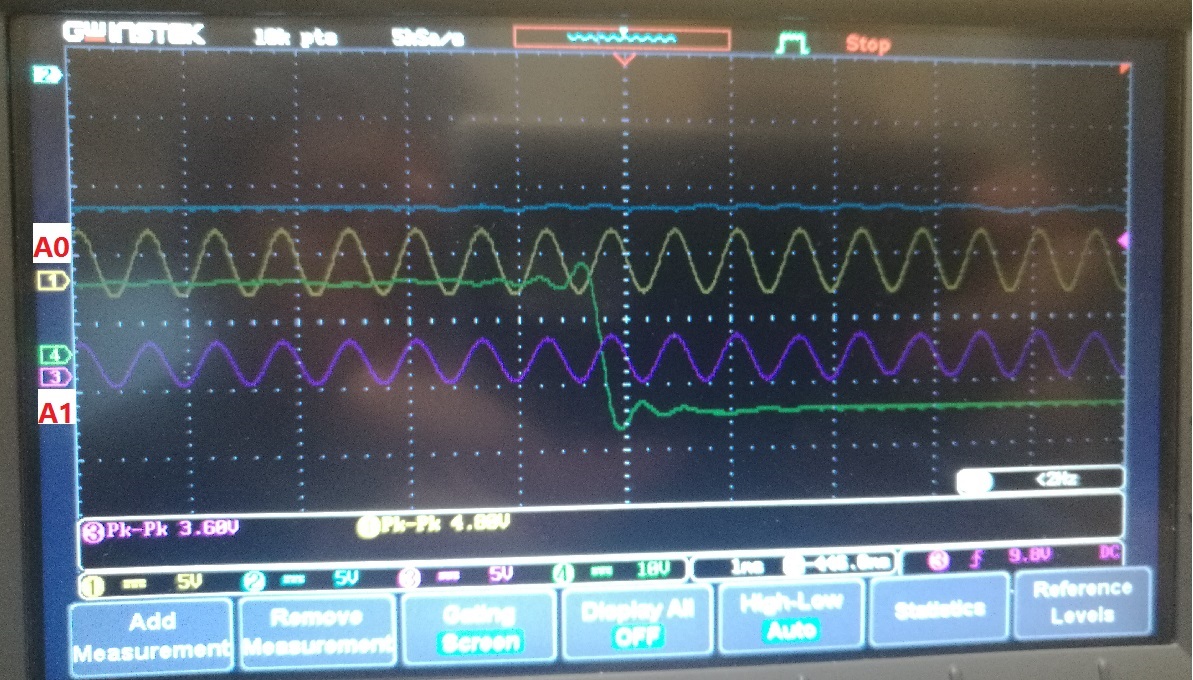
I'm not sure whether the A0 and A1 signals are measured perfectly or not.
The control signal is send from a national instrument DAQ PCI board and then the signals are buffered using DIP-24 ATF22V10C PLD.
I think the first step is to fix the address A1 problem.
Thank you!


