This thread has been locked.

If you have a related question, please click the "Ask a related question" button in the top right corner. The newly created question will be automatically linked to this question.

Starterware/DAC1282: DAC1282+ADS1282 to test detector leakage

Part Number: DAC1282
Other Parts Discussed in Thread: ADS1282,

Tool/software: Starterware

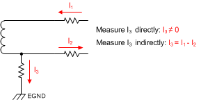
Hi, I am trying to use DAC1282 and ADS1282 to test the detector’s leakage, which has been written in the datasheet for seismic applications. However, I am still not sure about the official suggested circuit for the detector leakage test. Can I use the following circuit? If so, what should I do?

  • Hi,

    Which leakage current are your trying to measure?

    I don't believe we have a recommended circuit for measuring leakage current in this application. However, if you help me understand the type of leakage current you interested in, I might be able to provide some suggestions.

    Best regards,
    Chris
  • Firstly I was trying to measure the leakage impedance.

  • Hi,

    I think this could be accomplished with this circuit:

    The basic concept is that by comparing the voltage reading(s) on either side of the resistors you know the voltage drop across them. Form there you can calculate the current, knowing the values of the resistors.

    Best regards,
    Chris

  • Hi Chris:

     Thank you for your reply. However, what you proposed is the circuit to know the actual built-in resistance of the geophone, while I was asking to test the LEAKAGE resistance.

    Kenn

  • Hi Kenn,

    I'm afraid I need a bit more more information... Is the geophone earth-ground referenced? What other input circuitry (filter, protection, etc.) or components are you using? What is the main leakage current path that you're trying to measure?

    Likely, you could still use something similar to the above circuit concept; however, you will certainly need to tweak it to your specific application.  

    Best regards,
    Chris

  • We use the protection circuit recommended in the ADS1282 data sheet. The leakage current path is from the geophone to earth ground. The circuit between earth ground and analogue ground is not decided yet, which I think should be part of the leakage resistance test circuit.


    We can manage to test the leakage resistance using several external switches to build up a test circuit. Since TI provides ADS1282 and DAC1282 with internal switches and mux for AD and geophone test, I wonder if you have any suggestion for testing geophone leakage resistance with ONLY INTERNAL SWITCHES AND MUX, saving us use of EXTRA EXTERNAL SWITCHES.
  • Hi Ken,

    Sorry for the delay. I think you could adapt the above circuit to do one of the following measurements:

    Perhaps you could use the second ADC channel to measure the I3 current directly (across the resistor). If you wanted to measure I1 and I2, then you would probably need to use some external switches to measure make the connections across each of the input series resistors.

    Note that whatever source you use to provide these currents will need to be connected to earth ground.

    Best Regards,
    Chris

  • Dear Chris

    Could you please provide a precise equation of the group delay of the digital filter chain? The 31/fdata one on the datasheet is too rough for us.

    Best Regards,

    Ken

  • Hi Ken,

    Correct me if I'm wrong, but I don't think you can get a group delay much more accurate than 31/fdata. Group delay here is the amount of time it takes for a step input to propagate through the digital filter, so that the the amplitude change is seen in the output (but not settled). Here the conversion period (1/fdata) is the minimum step size in time.

    If it would help...the coefficients for the ADS1282's digital filter are given in an appendix at the end of the datasheet, if you wanted to try to plot the filter response in a program like MATLAB. I'm familiar with with finding the frequency response from the coefficients, but not as familiar with plotting the phase response and/or the group delay.

    Best Regards,
    Chris
  • Hi Chris,

    I think the group delay is much more accurate than 1/fdata. The digital filters are driven by a clock much faster than fdata. The actual group delay is related to clock frequency rather than fdata. Same applies to tdr (time to data ready), which has a very accurate equation. Actually we measured the group delay at 1k SPS. The result is 31.269 us to the accuracy of less than 1us. But we still need the theoretical equation to confirm our measurement.

    We did calculate the group delay using coefficients in the appendix. But this group delay is a purely theoretical. A more accurate equation should consider the actual digital circuit, such as the timing of registers.

    Best Regards,

    Ken

  • Hi Ken,

    I had to ask around for help on this, but I think we can provide some additional information on the group delay, likely specifying the group delay as a number of ADC clock periods.

    I'm waiting on someone else to give me this information, so it might be a day or two before I have response for you.

    Best Regards,
    Chris
  • Hi Ken,

    Here are the ADS128x group delay values for the linear-phase FIR filter:

    Group delay @ 4000, 1000, 500 sps = 30.21875000 samples – 244.000 CLKs
    Group delay @ 2000 sps = 30.21875000 samples – 240.000 CLKs
    Group delay @ 250 sps = 30.21875000 samples + 12.000 CLKs

    I hope that helps!

    Best regards,
    Chris
  • Hi Chris,

    Is the sinc filter included in these equations? if not, could you please provide equations of the whole filter chain?

    Moreover, could you please provide equations of the minimum phase filter (sinc filter included)? Only the group delay approaching DC is necessary, we can calculate the dispersion part ourselves.

    Thank you.

    Best regards,

    Ken 

  • Hi Chris,

    Our customer need us to verify specifications, such as THD, of both ADS1282 and DAC1282. Since we are not familiar with high precision DA/AD converter test instruments. If it's possible, could you please suggest a set of instruments (brands and models), as those used to test 128x series in your lab?
    Thank you.
    Best regards,
    Ken
  • Hi Ken,

    I'm looking into whether or not we have the data on the minimum phase FIR filter group delay...

    For testing you'll need a very low distortion generator and analyzer. I believe we use an audio analyzer from Audio Precision.

    Best Regards,
    Chris

  • Hi Chris,
    Than you for the recommendation on audio analyzer.
    How about the answer to the first question? Is sinc filter included in the group delay equations? If not, could you please provide equations for the sinc filter, or the whole sinc+FIR filter chain? The group delay calculated using your equation is about 1 ms smaller than our measured result, which is, if I'm right, the time between the effective sampling instant and falling edge of DRDY.
    Thank you.
    Best Regards,
    Ken
  • Hi Ken,

    Those group delay values include the SINC + FIR filter signal chain. Note that those are "average" group delay values, I think the actual group delay verses frequency has some ripple.


    user4687076 said:
    The group delay calculated using your equation is about 1 ms smaller than our measured result, which is, if I'm right, the time between the effective sampling instant and falling edge of DRDY.

    Yes, this would be exactly 1 conversion period at 1 kSPS.


    user4687076 said:
    Moreover, could you please provide equations of the minimum phase filter (sinc filter included)? Only the group delay approaching DC is necessary, we can calculate the dispersion part ourselves

    For the minimum filter, we only have measured group delay data at the 500 SPS data rate. Using a few different methods, the best result for the group delay was about 5.65 samples @ 500 SPS.


    Best Regards,
    Chris