This thread has been locked.

If you have a related question, please click the "Ask a related question" button in the top right corner. The newly created question will be automatically linked to this question.

ADS8568: Interpret Output Data Format from negative full-scale to positive full-scale

Part Number: ADS8568

Hi,

I'm working with the ADS8568 in Hardware mode with Serial interface and using all 8 input channels, and outputting all of them into the 4 data output pins.

My question is about understanding the output value that I'm getting. (Please help clarify how to read the Output Data Format). My test case is something like this: with VREF=2.5V and Range pin set to 2V, my input range should be -5V to 5V.

I expect to get my values to go from 0000h (@0V) to 7FFFh (5V) almost in a linear manner as I sweep my input voltage. HOWEVER, around 1.2V the output value goes back to 0000h and then up again then go back to 0000h again around 2.5V. Any reason why? Also it happens in negative values as well. I tried it with different output channels, but similar things happen but at different bit values.

In summary,

------ 5V (7FFFh)

  |   2.5V (0000h)

  |   2V (3xxxh) // some close number  

  |  1.2V (0000h)

  |  0.6V (3xxxh) // some random number again

  |  0V (0000h) 

  |

----- -5V (8000h) // similar thing happens but at some other values, so no clear pattern.

Thanks,

Ian

  • Hi Ian,

    Your expected behavior is correct, from the midpoint scale to full range, the output values should be from 0000h to 7FFFh

    The below table further explains expected behavior, it can be found in the datasheet.

    You stated that you are using all channels, this means you are reading the output for all channels; do all channels show the same behavior? Could you try checking each output at a time, maintaining the others off or stable at a known value?

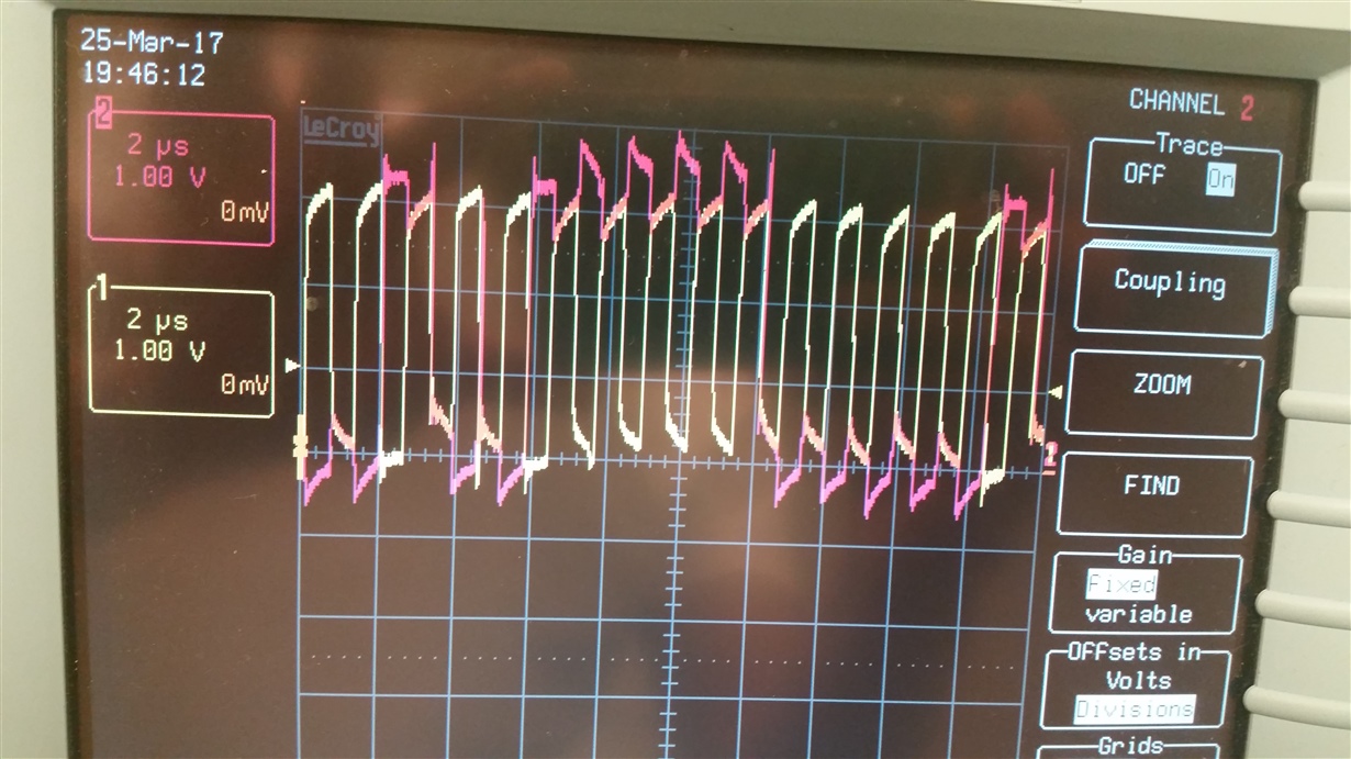
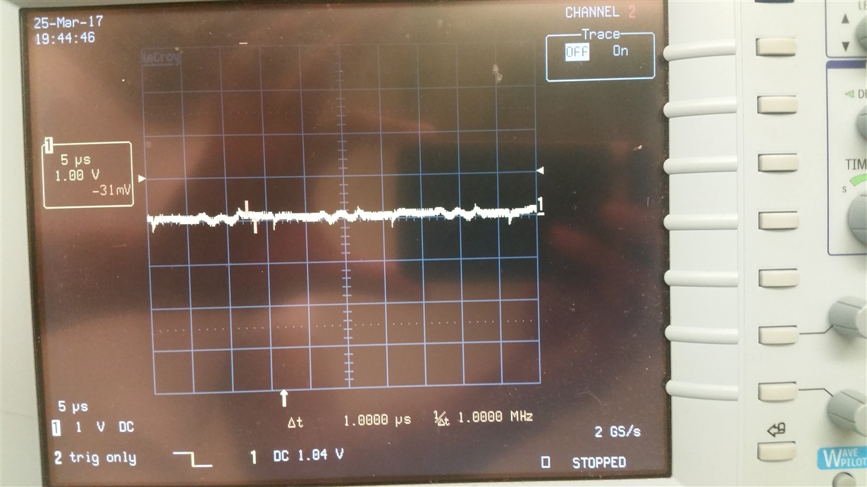
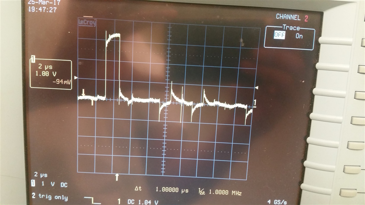
    Could you provide an oscilloscope shot for one pair CHx including, convertstartx, SDOx, sckl, SDI, busy, CS/FS? This will help further debug.

    -Best regards, Cynthia

  • Hi,

    Below are the images I took for Channel D. The voltage that I'm reading is 2.062V. All other channels behave similarly.

    When I read from the receiver pin, I read around 0x27e0. At the moment all of my channels read the same input, but the channels output behave differently around the middle: from 1FFF to 5FFF. But near the endpoints, I'm getting expected values such as 7FFF, 0000 and 8000. (The image filenames should have the description of each graph).

  • Hello Ian,
    Please keep your questions for same device in same post, Cynthia and I are working together to support and help you solve the issue. Please refer to your another query:
    e2e.ti.com/.../2144546

    Thanks.
    Best regards
    Dale