This thread has been locked.

If you have a related question, please click the "Ask a related question" button in the top right corner. The newly created question will be automatically linked to this question.

PGA411-Q1: PGA411 output wrong info

Part Number: PGA411-Q1

we occur a new problem when we test out product in simulative environment.


2 of our 4 boards didn't work normally. When the motor is still, the PGA411 on the two boards output wrong info.

The angular velocity and angular position is wrong and the AOUT either. The MCU got the wrong message and control the motor wrongly.

I have changed one of the two PGA411, and the phenomena keep the same.

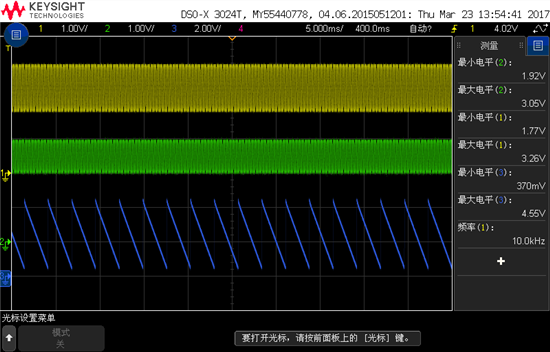
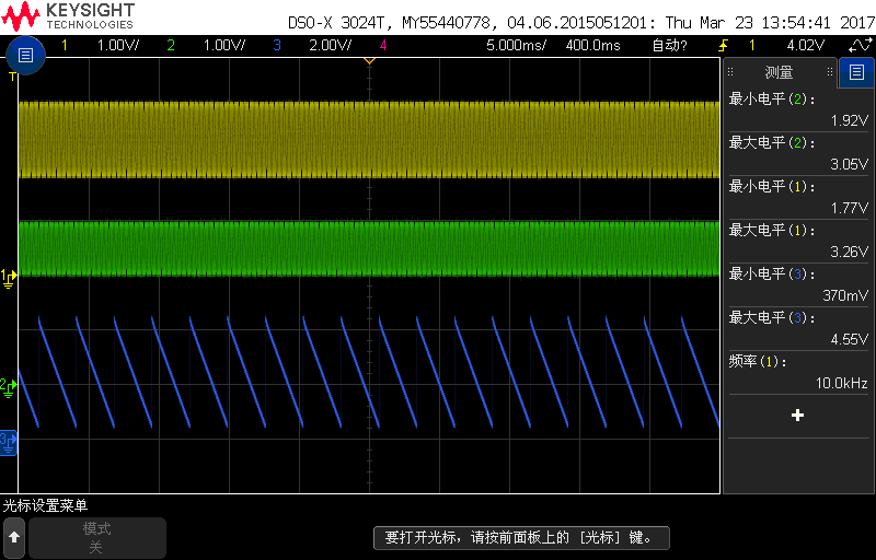
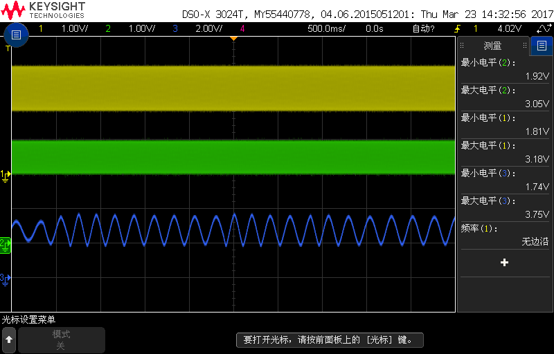
The image below is the waveform of OSIN(yellow), OCOM(green) and AOUT(blue) when the motor is still. And the output of AOUT is changing. 

The issue only occured when the motor is still.
Do you have any advise to solve it?
Many thanks!

  • Luffy,

    This means that the tracking loop is not locking properly. This can happen in a few different cases:

    - Improper IZx, IEx, OSIN/OCOS signal levels
    - phase offset register settings
    - resolver sensor is disconnected

    Can you provide more information so that we can resolve this?
    1. Do a read-all of the register settings on the PGA411 IC so that I can confirm the register settings are correct.
    2. At one of the boundary crossings (0, 90, 180, 270 degrees), please measure the Vpp of IZ1, IZ2, IZ3, IZ4, IE1, IE2, OSIN, and OCOS.
    3. Confirm that the resolver sensor is connected correctly.
    4. Zoom in on the OSIN/OCOS signals to look for noise.

    Please provide the register settings first so that we can cross that off the list.

    Thanks,

    -Clancy
  • hi Clancy,

    I'm Luffy's colleague,

    1.All the register settings are shown below:

    0 DEV_OVUV1 0x8000

    1 DEV_OVUV2 0x00FF

    2 DEV_OVUV3 0xFCC0

    3 DEV_OVUV4 0x07E2

    4 DEV_OVUV5 0x1C00

    5 DEV_OVUV6 0x038F

    6 DEV_TLOOP_CFG 0x0514

    7 DEV_AFE_CFG 0x0005

    8 DEV_PHASE_CFG 0x1400

    9 DEV_CONFIG1 0x0002

    10 DEV_CONTROL1 0x0000

    11 DEV_CONTROL2 0x0000

    12 DEV_CONTROL3 0x0003

    13 DEV_STAT1 0x0000

    14 DEV_STAT2 0x0000

    15 DEV_STAT3 0x0000

    16 DEV_STAT4 0x0002

    17 DEV_STAT5 0x4FBA

    18 DEV_STAT6 0x3FFF

    19 DEV_STAT7 0x004B

    20 DEV_CLCRC 0x00CE

    21 DEV_CRC 0x0000

    22 CRCCALC 0x00FF

    23 DEV_EE_CTRL1 0x0000

    24 DEV_CRC_CTRL1 0x0000

    25 DEV_EE_CTRL4 0x0000

    26 DEV_UNLK_CTRL1 0x00F0

    2.

    Vpp of IZ1 is 2.33V

    Vpp of IZ2 is 2.45V

    Vpp of IZ3 is 2.37V

    Vpp of IZ4 is 2.45V

    Vpp of IE1 is 2.17V

    Vpp of IE2 is 2.17V

    Vpp of OSIN is 1.97V

    Vpp of OCOS is 1.93V

    3.the resolver sensor is connected correctly.

    4.When Zoom in the OSIN/OCOS, there is no noise at all,as shown below.

    Thanks.


  • Howard,

    Thank you for the details. I double checked your register settings, and the autophase configuration looks correct. A few more questions:

    1. You mentioned that 2 out of 4 boards are exhibiting this behavior. What happens when you perform an A-B-A swap between these boards? The procedure is to swap the PGA411-Q1 ICs between a working board and non-working board. Then you test to see if the problem stayed with the PCB, or if it followed the IC. This will be very useful information.

    2. For the boards that are exhibiting this behavior. How often is it happening? Does it only happen at specific angles? If so, which angles?

    Thanks,

    -Clancy
  • hi Clancy,

    1.Until now,we made all together 5 boards.

    Board1,we never found this behavior.

    Board2,we only found this behavior once.

    Board3、4 and 5 all exhibit this  behavior,and the behavior are repeatable on these 3 boards.

    When we found this behavior on board3 , at first I thought it's the problem of this single IC, so I changed a new one on this board, but the behavior still exists.

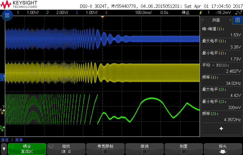
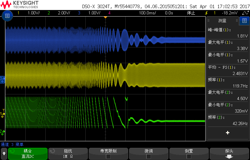
    2.Until now, we think this behavior happens randomly, we can't know if it happens at specific angles.Here are some waves I captured, maybe you can get something from these waves.

    the blue line and the yellow line are OCOS and OSIN.the green line is AOUT.

  • Howard,

    I appreciate your patience. Debugging issues like this is difficult, especially when I am not able to recreate the same problem on my boards. I have more tests for you to run that will help us pinpoint the problem.

    First, if possible please confirm that swapping the ICs between a board that reliably produces this problem and one that does not exhibit this problem results in the issue following the PCB (as your message suggests). If this is true, then we can work through each section of the PCB to find the problem.

    There are a few more tests that you can run:

    1.) Remove any protection diodes from the IZx pins. These can generate a small bias current, so it is best to rule this out as a potential cause.

    2.) change DEV_TLOOP_CFG to 0x0214, this will have the same affect as if AMODE is turned off. I do not expect this to fix the issue, but it is worth checking during the debug process.

    3.) If it is the PCB that is aggravating this issue, I wonder if it has something to do with the phase delay between the SIN/COS channels. An experiment to test this would be to take a working board and non-working board, and to swap all of the AFE components between the two boards.
    - This seems unlikely to be the issue on paper because it looks as if you are using tight tolerance components on the AFE as we suggest. I will do some investigation about this possibility on my end as well.

    4.) Remove the boost's inductor and diode and supply the VEXT/VEXTS node with a bench power supply. This will rule out that noise from the boost is causing issues. (this is also unlikely, but worth checking)

    5.) If you are using a DC/DC converter to supply the 5V rail for the PGA411, try running a test where your board is supplied directly from a clean 5V bench supply.

    The goal of these tests is to isolate the issue. Once we isolate the problem, then we can work on a robust solution so that you do not see this again.

    Thanks,

    -Clancy
  • 1.We removed all the protection diodes, the behavior still exists.

    2.We changed DEV_TLOOP_CFG to 0x0214, also we tried turning ON/OFF AMODE, the behavior still exists.

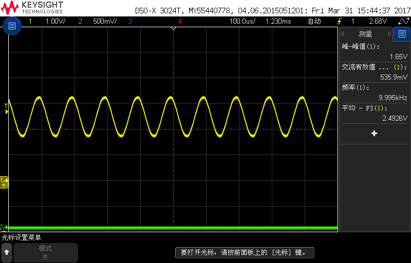
    3.I testd the phase delay, I think it's not obvious and will not influence the result. Here is the wave I captured.

    the yellow line is OE1,the green line is OSIN.

    after the test, I shifted all the AFE components from board 2(which has no problem) to board 5(which has the problem) and tested board 5, the behavior still exists.

    4.I remoded the boost's inductor and diode and supplied the VEXT node with a bench 12V power supply , the behavior still exists.

    5.The 5V power supply of the PGA411 is quite clean, the ripple is less than 50mV.

    Besides, during the tests, we found that the behavior had something to do with the angle, but for different board, the behavior happens at different angles.

    I hope these tests can help you to pinpint the problem, and we really want to solve this problem as soon as possible because we really don't have enough time left. If we can't solve this problem soon enough, maybe we have got to think of using other RDC ICs.

    Thanks.

  • Howard,

    Thank you for the quick response! I am eager to solve this issue as well.

    1. I couldn't see the filtering between VCC and QVCC on your schematic. What filter are you using?

    2. Since the phase delay is so low, it might be interesting to try the manual phase mode.
    DEV_PHASE_CFG = 0x2400

    Thanks,

    -Clancy
  • hi Clancy,

    Thank you for the quick response too!

    1.VCC and QVCC are from two different clean linear regulators, VCC is 4.98V while QVCC is 4.97V by test.

    2.We set  DEV_PHASE_CFG = 0x2400, and the behavior disappear...All the 3 boards are the same.

    So I think we can say the problem has been solved for now.But I still have some doubts,

    1.Why the Auto-mode phase delay correction will cause this kind of behavior?Is it a bug of the IC?

    2.Why some of the ICs have this problem but some don't?

    Thanks.

  • Howard,

    My team is working on the answers to those questions. The analysis may take a little time because we need to involve our design engineers, and the analysis will require further testing on our end.

    I have another question for you. Were any faults occurring when this loss of tracking happened? Or were you ignoring faults by keeping FAULTRES low?

    If no faults occurred, then try lowering the LPETHL and LPETHH thresholds until errors do start occurring during the loss of tracking event.

    Thanks,

    -Clancy
  • Clancy,

    1.During all the tests before, no fault occurred when the behavior happened.We never kept FAULTRES low.

    2.After we lowered  LPETHL and LPETHH to 0.25V, the FLOOPE error occured when the behavior happened.

  • Howard,

    I've discussed this more with my team and we have a few more questions:

    - Have you tried running at different speeds before stopping the motor? Does there seem to be any dependency? Will the issue happen if the motor is turned very slowly or hand turned before stopping?
    - Is the frequency of the AOUT oscillation consistent, or is it different each time the issue occurs?
    - The OSIN signal in the phase delay waveform you shared looks a little noisy. Is that true or is it an artifact of the oscilloscope?
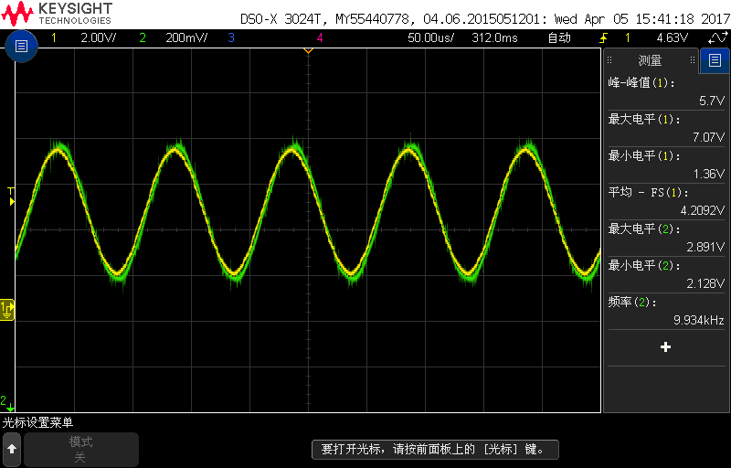
    - In the top plot from April 4th, did the AOUT eventually settle into the sawtooth waveform that you've shown in other plots?

    Thanks,

    -Clancy
  • Clancy,

    1.We tried running at different speeds, I think there is no dependency.

    The issue happens when we turn the motor with hand very slowly,even a very slight hand turn can cause the issue.

    2.The frequency is not consistent, it varies with time flowing.

    3.The noise is not true, it's an artifact of the oscilloscope.

    4.No. The behavior has two main different forms as shown below,

    the first one, as you know, sawtooth wave form,frequency varies with time.

    the second one is like this, the amplitude shrinks with time,after a period of time,the amplitude is near to zero.

  • HI Clancy,

    It‘s been a long time since we discussed the question last time.

    I want to know if there is any progress about this question.

    And I need to make sure that if there is any risk if we use the PGA411 in our product. We found this question, so we don't know if there are some other problems in the IC and we worry that if we use it in our product, some unknown problems may occure , which is not acceptable.

    So I hope to get more information from you about the question.

    Thanks a lot.

  • Howard,

    I have seen similar issues at other customers, but every time the issue comes down to the fact that the AUTOPHASE_CFG setting is not set to b00, which we know can cause problems. Can you please double check this setting on your boards? Do a read back of the PGA411 to make sure of the settings.

    I sent a message to your colleague privately about the possibility of you sending us one of your boards so that I can test the issue here. Would that be possible?

    Thanks,

    -Clancy
  • Clancy,

    Next week we will do the double check about the setting.

    But I'm confused why the auto-phase behavior will cause such bad behavior.

    Our board is not a demo board, there is no extra port for external controllers, and the mcu we use is a Fresscale DSP MC56F8366, I don't know whether you can use it.

  • Howard,

    Have you had a chance to double check the register setting?