This thread has been locked.

If you have a related question, please click the "Ask a related question" button in the top right corner. The newly created question will be automatically linked to this question.

Please help with selection of ADC for custom PCB-mounted Search Coil (arduino board)

Other Parts Discussed in Thread: ADS131E04, ADS131A04, ADS1256, ADS1262, ADS1220, ADS1292, ADS1257, ADS1291, ADS124S06

Hello, 

I'm working on a project for long-range magnetic field sensing of current carrying wires. 

We're trying to detect energized distribution and transmission lines 10 or more feet away.

We've had pretty good luck using commercially available magnetometers like the MMC34160PJ Magnetoresistive 3-axis I2C magnetometer, but we still want better accuracy than 0.5mG/Count.

We're working on implementing a small 23 x 13 mm search coil with about 500 turns (still have to calc. this) using AWG 44 magnet wire.

Our goal is to interface the search coil with an extremely high-resolution ADC (>= 20bit) and successfully observe sinusoidal magnetic fields in the 1-micro-Tesla range.

Can you please recommend an external ADC you've had success with with the following requirements:

  • No 50 or 60Hz rejection.
  • 4 channels
  • small SMD package
  • 24 bits or higher resolution
  • extremely low noise
  • 1800 Hz sampling rate per channel.
  • Easily interfaced with ATMEGA328P (I2C or SPI)
  • < $10

Any other suggestions on the project is greatly appreciated!

JT

  • Hi John,

    welcome to our forum and thanks a lot for your interest in our ADCs.

    While I don't really have experience with the type of application you are working on, I can probably suggest a few ADCs that might meet your requirements. From your description it was not 100% clear to me if you need to measure all four signals simultaneously. If you do we have options for that as well.

    24-bit, 4-Ch Simultaneous Sampling ADCs:
    - ADS131E04
    - ADS131A04

    24-bit, >=4-Ch multiplexed ADCs:
    - ADS1256
    - ADS1262

    Regards,
  • Hi Joachim,

    The ICs you've suggested are very large and look quite advanced to setup and program. I'm looking for something in a much smaller package as this will be in a wearable device (26 mm circular PCB)

    Also, the ADS1256/62 have 50 and 60 Hz rejection listed as a feature. Is this something I can easily disable?

    Also, is there another forum this topic would be better suited for?

    Thank you for the reply!

    John
  • Hi John,

    for questions around ADCs you are in the correct forum.

    The problem is that your requirements are quite demanding and call for some of our higher-end ADCs.
    The ADS1220 would be our smallest 24-bit ADC (3.5x3.5mm QFN) but it only offers data rates up to 2kSPS.
    The ADS1292 might be something to consider, but it would require an external multiplexer then.
    The ADS1257 is a version of ADS1256 in a 5x5mm QFN but will also require an external multiplexer to measure 4 signals.

    The 50/60Hz rejection in our ADCs does come kind of for free when you select an output data rate of <=20SPS.
    If you use higher data rates the internal digital filter will not reject 50/60Hz noise. Means for higher data rates, the 50/60Hz rejection is 'disabled' if you want to say it that way.

    Regards,
  • Hi Joachim,

    If i were to change the requirements to only 2 or 1 channel, how would your recommendations change?

    The ADS1257 looks quite attractive to my application! Thank you!
  • Hi John,

    if 1 or 2 channels are sufficient then I would probably look at ADS1291 or ADS1292 (or ADS1220 if you could live with lower data rates per channel).
    The ADS129x offers great noise performance at the low power it consumes. At this power level it is probably one of the lowest noise ADCs you can find on the market. Plus you could measure both signals simultaneously without having to worry about multiplexing.

    Regards,
  • Hi Joachim,

    I'm going to move forward with working with the ADS1292 as it meets the majority of my requirements.

    The next steps are learning the minimum component hardware build and finding working open-source Arduino drivers.

    JT
  • Hi John,

    sounds good to me.
    I don't think you will have much luck finding Arduino drives for ADS1292 (at least not from TI). Let me see if we have at least some example code available that we could share with you.

    Regards,
  • Joachim,

    The ADS1257 looks much simpler to setup, but it looks like the minimum analog voltage supply is 4.75V, whereas our device operates on a Lipo battery pack operating in the 3.7 - 3V range.
  • Hi John,

    I would not necessarily say the ADS1257 is much simpler to set up. The ADS1292 might look a little overwhelming at first sight due to all the special features it offers for ECG applications. You don't need to use any of those.
    The ADS1257 was not designed with battery-powered applications in mind, but instead traditional industrial applications which primarily used 5V analog supplies at that time.
    The last option that you could look at would be the ADS124S06.

    Regards,
  • Hello, 

    Please review my minimum component build for the ADS1292, attached below:

  • Hello John,

    I am the expert for the ADS1292 so I can work with you from here. I see only two things that you need to address:

    1. You will not be able to connect IN2N to ground. The ADS1292's internal PGA is output limited to AVSS + 200 mV. The PGA is a fully differential amplifier whose output common-mode voltage is the same as the input common-mode voltage. You can find a formula which defines the range of the input common-mode on page 22 of the datasheet in Equation 6. Instead, you'll want to bias IN2N to some voltage within that range, ideally mid-analog supply (AVDD + AVSS)/2. This can be done with a simple voltage divider, or, if the resistor tolerance will not provide you with enough accuracy, you can leverage the ADS1292's built in op-amp (called the RLD amplifier). Let me know how you think you would like to do that and I can assist you.
    2. We recommend tying the GPIO pins to GND if unused.

    In terms of sample code, there is a TI design that uses the ADS1292 with the MSP430 which contains some code, but unless you are using the MSP430, it may not be useful. The ADS1292 uses regular SPI so perhaps you could leverage a more generic SPI library.

    Regards,

    Brian Pisani

  • Hi Brian, 

    Thank you for the prompt reply!

    Please disregard the connection for IN2. My first step is to just successfully reading high-resolution data from a micro search coil. The expected signal range for this is a +/- 1x10^-6 V amplitude bipolar sinusoidal. 

    Please assist me in the appropriate configuration of the ADS1292 in order to measure this. 

    Here's some more info on the application:

    • This is a wearable device operating from a  3.7V LiPo battery, so the analog and the digital supply is 0 to +3.7V.
    • Interfacing to an ATMEGA328P microcontroller running an Arduino bootloader.  
    • I'll be writing the SPI driver from the datasheet,  and reference materials. 
    • I'm trying to strive for a 'minimum component' design solution. 
    • I'll be using the Arduino IDE and SPI library.

    I was assuming I would be able to measure a bipolar input using an analog supply of 0 to +3.7V. Will I have to offset the input to (AVDD + AVSS)/2?

    I'm not familiar with the RLD amplifier, and I was honestly confused when reading about it in the Datasheet. 

    Thank you again for your assistance! We're excited to learn how to use TI high-resolution ADCs and are excited to overcome this design problem so we can release our product ASAP.

    JT

  • Also, I have a few more questions:
    1.) Can you operate the ADS1292 without an external Oscillator? The datasheet states that there is an internal oscillator running at 512kHz, which seems pretty slow for SPI to me. I know that to use the internal Oscillator you have to connect CLKSEL to DVDD.
    2.) Do the SPI communication lines need any pull-up/down resistors?
    3.) To offset an input signal (INxN) to (AVDD + AVSS)/2, we can use a voltage divider using two same-value resistors. What value of resistance is best to avoid any 60Hz filtering, yet reducing any leakage currents?
  • Hi Brian, 

    Here is my revised layout with GPIO grounded, and an offset applied to IN1:

  • Hello John,

    It may be dificult to measure 1 uV with a 1.8 kHz sample rate without some digital filtering on the back end. As you can see from Tables 1-5 in the datasheet, the best case noise that the data converter can provide for 2 kSPS (as close to 1.8 kHz as we can get without changing the clocking) is 1.9 uVrms (14 uVpp).

    What does the sensor look like? You have biased the input using a voltage divider, but with a differental sensor output like the one you have, it may already be biased. Biasing one of the inputs with a voltage divider will allow noise from the power supply to couple in through the inputs. If the sensor is already biased, then any noise that comes from the power supply will be common to both inputs and will be cancelled by the chip's CMRR.

    I can answer the questions you asked:
    1. Yes you can use the internal oscillator. The SPI and the other internal circuitry run independantly so there is no need to worry about the internal clock speed as it relates to the SPI frequency (except as it relates to command decode time - see the SCLK section on page 28).
    2. No they are all push-pull.
    3. See my answer above. This may not be necessary nor desirable for a differential input scheme.

    Regards,
    Brian
  • Brian, 

    Filtering on the back-end? Do you mean some sort of digital filtering? That's possible. 

    1.8kHz isn't absolutely necessary, I was just wanting 30 samples per cycle for a 60Hz sinusodal signal. 10 or even 4 samples per cycle could be good enough.

    The sensor is just a custom 20x30mm air coil with probably 1500ish turns. I wasn't counting when I wound it for 1.5 hrs using 44 AWG magnet wire :).

    I don't anticipate there being any noise from the 3.7V lithium ion battery pack as the circuit is quite efficient (low current draw).

    JT

  • Hello John,

    Yes I am referring to digital filtering.

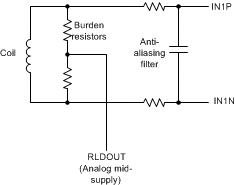
    If I am understanding correctly, the coil is inducing a current from the magnetic field. Are you transforming that current to voltage through a burden resistor? If so, you can actually "tap" the burden resistance in the middle with the on-chip op-amp (RLD amp) output to bias the sensor in a common-mode manner. I drew a picture of what I am thinking:

    Does this make sense? In this setup, you can scale the burden resistors to provide a larger voltage (assuming the current is constant). Using a larger voltage will make it so you are less worried about noise.

    That battery will probably have some noise :-). In any case, if you use the setup I drew above, any noise generated by the RLD op-amp will be common-mode and thus will be cancelled by the ADC.

    Regards,

    Brian Pisani

  • Brian,

    I think you guys have more than answered my original question which was just verifying the hardware setup of the ADC, learning more about it's capabilities, and input biasing, thank you for the great feedback.

    The air coil produces an induced voltage when there is a changing magnetic field through the coils, and so it's open-circuit (high impedance) in my circuit. I might add some sort of impedance-matching eventually to try and achieve the largest voltage output from the coil, but I'm not that far yet.
  • John,

    If the output of the sensor is voltage, then there is no need for the burden resistors to measure the signal. However, you can still include them if you make them large value. That way you can still bias the inputs to provide a differential input voltage to the ADS1292 which is the best option in terms of noise performance. Keeping the resistance high will make it so the sensor does not have to drive much current.

    Regards,
    Brian Pisani