This thread has been locked.

If you have a related question, please click the "Ask a related question" button in the top right corner. The newly created question will be automatically linked to this question.

DAC8775EVM: Configuring Power Supply and Jumper Settings

Part Number: DAC8775EVM
Other Parts Discussed in Thread: DAC8775

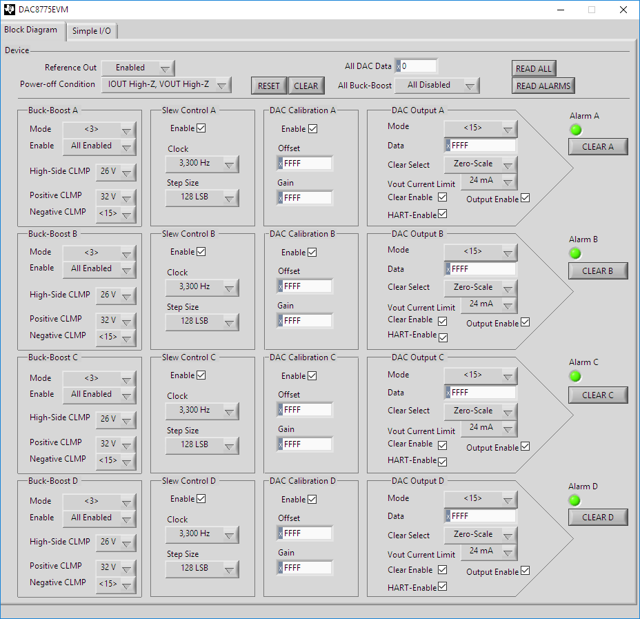
After issuing a Reset (or Read All) command in DAC8775EVM software, all channels alarms are activated, as shown in the screenshot below, and can not be cleared. What changes should we make to the supply/jumper settings in order to clear the alarms?

The following are the current (default) board jumper settings*:

- An external supply of 12V is connected to J2 and all jumper settings are in default factory-setting positions for single external supply

- SM-USB-DIG supply to DVDD -  JP9 and JP11 installed while JP13 Not Installed

- Selects the DAC8775 internal reference JP10

- DC/DC Channel A to supply VPOSA and VNEGA

* Note: we are not clear on how to interpret 3-pin jumper position (1-2 "inner" vs 2-3 "outer") 

Also, please note that "Clear Enable" and HART-Enable" UI check-boxes for Channels B and C seem to be "Read-Only" and can not be changed.

Thanks for your help.

  • Issue is resolved: The alarms are cleared by reconnecting SM-USB-DIG to J1 before connecting USB cable to host.

    * The UI issue remains (unable to set Clear and HART Enable of Channels B and C) , likely require an update to the software. Is there a way to bypass the LabView UI and drive the EVM directly (Is there an example or an application note on using SM-USB-DIG via standard programming languages)?
    * Other than tracing the circuit diagram and board, are there markings that might help in quickly figuring out the 1-2 "inner" vs 2-3 "outer" settings of the 3-pin jumpers (Samtec TSW-103-07-G-S)?
  • Lasto,

    Your comments regarding the state of the GUI without connecting the SM-USB-DIG to the EVM seem valid to me. Without the connection the SPI pins of the DIG are all floating and therefore I could see them returning values in-line with what you have shown in the GUI screen capture.

    To be clear - the issue you have with CH B and CH C are that you cannot issue a clear command to either channel and, additionally, you cannot enable the HART input pins? It is possible there is some issue with the GUI but both commands basically call the same subroutine as they would for CH A or CH D so I'm just curious to make sure we're on the same page in order to try to debug this or dig deeper.

    SM-USB-DIG isn't really documented as a "development platform" as it's intention was just to be used with the EVM GUIs. It's a simple USB HID device, though, so it's not all that complex to interface with. Let's try a first pass of the questions above and double-checking our software before we go down this path, though. I'd hate for you to develop some interface only to uncover that there was some innocuous problem under the surface.

    Generally speaking jumpers are marked on the top side with a circle by pin one. Alternatively, if you flip the board over the underside of landing pattern is marked with a square while the other pins are circles.

    Could you describe / photograph your EVM connections so we can verify your HW configuration?
  • Kevin,

    Thanks for your response. The EVM and all DAC channel outputs are working fine after the alarms were cleared, so the jumper (factory) settings were OK.

    * The issue seems to have been related to the "order" in which the cable is connected to the EVM board and host computer; per the EVM manual "This error can also occur if the USB cable is connected before the SM-USB-DIG platform power source." The software does not seem to issue an error in our case (so, we thought it was jumper issue or defective SM-USB-DIG)

    * The Clear/HART UI checkboxes for Channels B and C still do not work (continue to be read-only). The data setting textfields and actual measured output voltage/current are working fine. Likely, minor UI issue.

    * We fully understand that SM-USB-DIG is not a development platform, but interface examples or documentation could help us create simple additional evaluation scenarios (e.g., switching and ramps of digital data values).

    * We found the square markings at the underside (the markings at the top of the jumpers, next to all pins, are all circles - it seems that 3-pin jumpers were split from longer/bulk header strip).

    Thanks a lot for your help.
  • Lasto,

    I ran through the GUI code yesterday and couldn't see any reason why channels B and C wouldn't be functional in the same way as channels A and D or other bit-fields that share the same register location as the HART-ENABLE and CLEAR-ENABLE bits so I'm somewhat at a loss initially. I have some material on hand but to be totally sure we're going to order an EVM from the release-stocked material so we can run code-traces etc. to validate whether there is some issue with the released material. We should be able to close this out with you sometime early next week.

    As far as communicating with the DIG goes, it's all actually a very simple mnemonic structure. We have supporting VIs in LabVIEW that I can probably describe to you simply within the context of just communicating with the DAC8775EVM but I'm not sure that you'd be using LabVIEW as a development environment. Describing the full details of the USB-HID device would take a bit more time to document. Most likely we would have the conclusion of our investigation before a complete document could be completed.