This thread has been locked.

If you have a related question, please click the "Ask a related question" button in the top right corner. The newly created question will be automatically linked to this question.

ADS1298: Run test signal and measure heart rate using 2 electrodes

Part Number: ADS1298
Other Parts Discussed in Thread: ADS1291, ADS1292, ADS1296, ADS1294

I'm trying to communicate to ADS1298.

first of all I sent SDATAC

Next, I read chipID and got correct value.

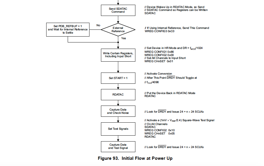
After that I wrote and read configs according to datasheet page 85, so I'd like to use internal ref for this I set CLKSEL to high and write this:

WREG CONFIG3 0xC0
WREG CONFIG1 0x86
WREG CONFIG2 0x00

// I have 8 channels and set all to 1 WREG CHnSET 0x01

It's time to set START pin to high and send RDATAC
I'm a little bit confused with this note from datasheet look for DRDY and Issue 24 + n * 24 SCLKs

Do I need to skip 24 times before reading or I have to read 24+8*24 = 216 cycles?

So, I captured my signal and got this image

I drew this graph using Processing which got events from serial (I put DOUT data to uart)

It looks the similar a little bit on squared signal but not sure. If I got an event that my DRDY is changed do I need send SDATAC before reading converted data? And how long I should hold start pin high? And every time when I call RDATAC I also have to set START pin high?

And the second question, I wanna try to get heart rate using 2 electrodes, do I need to connect RLDINV to each one via resistors?

  • Hello Ivan,

    The process should go like this:

    Send SDATAC;
    Write registers;
    Send RDATAC;
    Send START or pull START pin high;
    
    while(1){
    	if(DRDY == 0){
    		Pull CS low;
    		Toggle SCLK 216 times;
    		Pull CS high;
    		Do what you need to do with the data;
    	}
    }

    So you see you actually only need to send RDATAC and START at the very beginning and then from then on you just wait for DRDY to transition low to collect data. Is this what you are doing?

    Also if you just want to do single lead ECG, have you considered using the ADS1291? You will need to bias the inputs so if you only plan on using 2 electrodes then you should connect RLDOUT to the input pins through large resistors to bias them. Feel free to send me your schematic to review if you plan on creating another board. 

    Regards,

    Brian

  • it means that i have to receive 27 bytes (216/8), I configured registers as you showed above and read first 27 bytes when my DRDY is toggled to low (according to data sheet this line issued to low for a long time while I'm reading DOUT?), next I

    send SDATAC
    reconfigured registers CONFIG2 and each channel according p.85
    send RDATAC

    After that I'm reading the values.
    I expect 27 bytes (first 3 is header and 3 bytes for each channel)

    uint8_t in[27] = {0x00}
    uint8_t out[27];
    ...
    for (int i=0; i< 27; i++)
    {
    out[i] = readMISO(in[i]);
    }

    but I captured image for all channel, guess I need to capture data for each channel (I need to send via serial 3 bytes for each channel), am I right?

    And I would like to use ADS1298 for 2 goals: measure heart rate and measure EMG

    I'm planning to switch between electrodes for heart rate and EMG using MUX, is it possible to use ads1298 instead of ads1291
    Maybe not use 2 lead electrodes (cause I don't want tie RLDOUT to inputs), can I use for instance 3 electrodes?

    INP, INN and RLDOUT as reference? or what is minimal numbers of electrodes I should use for heart rate of ads1298?
  • Hello Ivan,

    Why do you need to change the CONFIG2 and channel registers in between each sample? Can you not just configure it to the desired setting at the beginning and then only capture data after?

    If you just need to measure 2 signals, I recommend the ADS1292 which is like the ADS1291, but with 2 channels. There is no need to use a mux - the device has 2 simultaneously sampling channels. Each time the DRDY signal is sent, both channels' conversion results are in the output data.

    Brian
  • Hi Brian, thanks for your patience!

    Of course I can, but I wanna simulate a test signal and data sheet recommends to use this settings

    When I sent RDATAC I should reconfigure CONFIG2 and channels to get square-wave signal, to be sure everything is working

    I remember you already recommended me to try ads1292 and I found it suitable, but I'm looking for a solution for a small board size, and it would be perfect that one chip like ads1298 could measure electromyography (wanna measure muscles) and heart rate. Unfortunately ads1292 has only 2 channels and I need to know potential of 8 points of muscles. To have 2 chip on board it's very uncomfortable.

    I found that I can use 2 electrodes of ads1298 for HR but I can't understand how to place RLD electrode not for leg. I guess I need other electrodes tie to high level, am I right or can I programmatically disable electrodes for this purpose?

  • Hello Ivan,

    It is not necessary to do the input short test before you capture the test signal. In addition, the portion that says "Look for DRDY and Issue 24 + n x 24 SCLKs" should be repeated several times. When you are collecting data, you need to collect multiple points. When the device is configured properly, all you need to do is wait for DRDY, then toggle SCLK, collect the data, and then again wait for DRDY. There is no need to re-configure the device each time you collect a single data point.

    I was not aware you had to collect more that one channel's worth of EMG data. How many channels do you need? We have 1, 2, 4, 6, and 8 channel versions of these devices. They are the ADS1291, ADS1292, ADS1294, ADS1296 and ADS1298, respectively.

    Generally the RL electrode is a dedicated electrode rather than being another electrode that you use both for measuring and driving. Where are you planning to connect the electrodes for heart rate measurement?

    Brian
  • Hi Brian!

    Yes, I understand that I don't need to do short test when I capture a real signal, it's just for understanding that the board works well. I expected square wave when I had configured registers for test. I attached the picture of my data (that I got from DOUT when DRDY became low) this picture shows unpredictable behaviour of signal. Should I split data for each channel? For example I got 27 bytes, 3 of this are some header, next 24 bytes are data. If I expect data of each of 8 inputs,do those 24 bytes contains data for all 8 inputs (3 bytes for channel)?

    Sorry for confused you, I described a little bit wrong my idea. The main goal is to get working EMG system to use all 8 channels (to be honest I need 16 channels and I'm going to use 2 ads1298 in the future). Also I read that this chip is suitable for ECG measurement. And I made up the second goal to add a possibility to use this chip also as heart rate monitor. For example, in main loop I read a signal for EMG of all 8 channels. Once in n minutes I stop the conversion, reconfigure registers and read the heart rate. After that I stop it again, and measure EMG.

    And I'm looking for possibility to measure heart rate for minimal numbers of electrodes, ideally it would use 2 electrodes for this purpose. I could use 1 INPP and 1 INPN for both cases, EMG and heart rate and switch between them when I need.

    I'm planning to put electrodes on chest.

  • Hi,

    First of all you need to read all the bytes, always. In case of ADS1298 you must read 27 bytes whenever you get a signal from DRDY (if the data rate is lower than 32kSPS, see page 53 of datasheet: Readback Length).

    About EMG and ECG, actually I don't know what you mean by stopping EMG and measuring heart rate. If in your application measuring EMG should be real-time, you actually don't have time to do so. Heart rate is usually measured in a frame. So it is not a sample. You probably need to measure ECG for 30 seconds for example to calculate the heart rate. It might be worth to take a look at the transient time of the chip too (See table 12 of datasheet). Additionally, what configurations are different between measuring EMG and ECG? Is it more than data rate? I believe no.

    Here is my idea in more details. You measure the signal (whatever signal) from chest with high data rate so it can contain EMG too. Then this signal contains both ECG and EMG (and even some other signals). They are different just in bandwidth. So you filter the measured signal with a low pass filter with a cut-off of e.g. 70Hz to get ECG, extract the R-peaks and then calculate the heart rate. And apply another filter (probably more complicated depending on the EMG bandwidth of interest) to remove the ECG from the same signal to get EMG. Basically when you measure a physiological signal you can find footprints from all the electrical sources in the body. For instance sometimes even in EEG you see R-peaks from heart activity. So why switching from "EMG measurement" to "heart rate measurement"?

    I would do all these stuffs after measuring some signals and off-line. Measure some signal from the electrode location that you want, record the signals, take them to MATLAB for example. Design your signal processing pipeline and finally convert them to whatever system suitable for your MCU. There are many issues to consider here for example the timing since the data rate is high and the signal processing that we are talking about is not computationally cheap.

    About RLD, I would say you don't need it for heart rate. Although you might find it helpful for EMG measurement. Of course you should check the outcome of your measurement because there can be many factors affecting the quality of the ECG signal and therefore and accuracy of the R-peak detection and finally the accuracy of heart rate estimation. Additionally for RLD you need one more electrde (three electrode at least)

    Hope this helps

  • Hello Ivan,

    Hopefully Vala's comments were helpful as to the algorithms you can use for your system. I am not an algorithm expert, so I can only comment on how to use the ADS1298.

    Yes the data needs to be split out by channel. When you get the data it will be like this:
    3 bytes status | 3 bytes CH1 data | 3 bytes CH2 data | 3 bytes CH3 data | 3 bytes CH4 data | 3 bytes CH5 data | 3 bytes CH6 data | 3 bytes CH7 data | 3 bytes CH8 data

    This data is just one sample for each channel. To get the individual channel's data, you will need to implement some logic to store the data separately and in a signed format (since the output can be a negative number if the MSB is 1).

    Since the test signal has a frequency of about 1 Hz, you will need to collect about 500 samples to get a full period of the test signal. Then, to plot the test signal for only channel 1, for example, you need to take the series of 500 channel 1 data points corresponding to "3 bytes CH1 data" above and plot them with respect to time. The time scale will be each sample corresponds to 1/500 Hz = 2 ms per sample. Does this make sense?

    Brian
  • Thank you Vala, Brian. Now everything is clear. Gonna catch the ECG signal first. Wanna try to catch it programmatically cause I don't want to include resistor and capacitor for low pass filter for DOUT.
  • Hi Ivan,

    Just wanted to clarify a couple of points for you. Of course for some digital filters you can alternatively use analog ones, but not in your case. There are two reasons. One is that you need to have both ECG and EMG signals after sampling your analog signals and if you filter them using an analog filter you cannot have them both. Another reason is that, I guess the filters that we are talking about are not simple enough to be implemented using analog components.

    Another point is that even if you wanted to have an analog filter, you should put it in your analog chain and before sampling your analog signals not on DOUT, which is a digital signal.

    And finally, I guess you know that you should have some analog filters before the AFE anyway for antialiasing and patient protection purposes.

    Vala