This thread has been locked.

If you have a related question, please click the "Ask a related question" button in the top right corner. The newly created question will be automatically linked to this question.

ADS1293: ADS1293 FOR ECG ,NOise issue

Part Number: ADS1293
Other Parts Discussed in Thread: MSP430F5529,

Hi boss

I  use the ADS1293 for PPG Monitor, when the input is the pulse generator, the ADC reading is ok

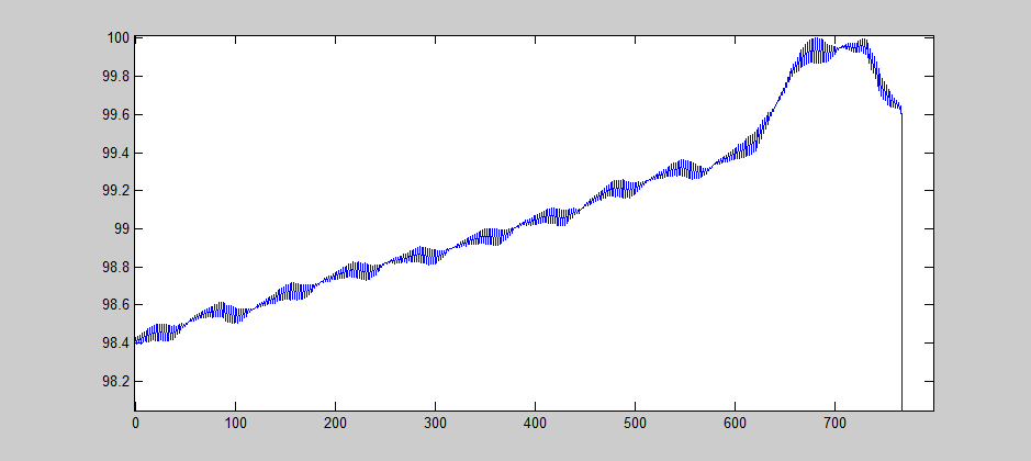
but I use the dry contact from the human body.I found the ADC reading have a wrong value as below.

I already enable digital filter.i found the data have the dc bias,

thanks

  • Hello Alex,

    Can you provide your schematic and register settings?

    Regards,
    Brian Pisani
  • void TI_ADS1293_WriteRegSettings(void)
    {
    TI_ADS1293_SPIWriteReg(0x00, 0x00);
    TI_ADS1293_SPIWriteReg(0x01, 0x11); //IN1?CH1- ,IN2?CH1+
    TI_ADS1293_SPIWriteReg(0x02, 0x19); //IN1?CH2- ,IN3?CH2+
    TI_ADS1293_SPIWriteReg(0x03, 0x00);
    TI_ADS1293_SPIWriteReg(0x04, 0x00);
    TI_ADS1293_SPIWriteReg(0x05, 0x00);
    TI_ADS1293_SPIWriteReg(0x06, 0x08);
    TI_ADS1293_SPIWriteReg(0x07, 0x00);
    TI_ADS1293_SPIWriteReg(0x08, 0x00);
    TI_ADS1293_SPIWriteReg(0x09, 0x00);
    TI_ADS1293_SPIWriteReg(0x0A, 0x07); // set Common mode (IN1. IN2. IN3)
    TI_ADS1293_SPIWriteReg(0x0B, 0x00);
    TI_ADS1293_SPIWriteReg(0x0C, 0x04); //通道IN4 ?右腿??
    TI_ADS1293_SPIWriteReg(0x0D, 0x00); // WILSON EN IN1
    TI_ADS1293_SPIWriteReg(0x0E, 0x00); // WILSON EN IN2
    TI_ADS1293_SPIWriteReg(0x0F, 0x00); // WILSON EN IN3
    TI_ADS1293_SPIWriteReg(0x10, 0x00); // WILSON Ref connected IN6
    TI_ADS1293_SPIWriteReg(0x11, 0x00);
    TI_ADS1293_SPIWriteReg(0x12, 0x04); // OSC Control
    TI_ADS1293_SPIWriteReg(0x13, 0x00);
    TI_ADS1293_SPIWriteReg(0x14, 0x00);
    TI_ADS1293_SPIWriteReg(0x15, 0x00);
    TI_ADS1293_SPIWriteReg(0x16, 0x00);
    TI_ADS1293_SPIWriteReg(0x17, 0x05);
    TI_ADS1293_SPIWriteReg(0x21, 0x02); // R2 rate=5
    TI_ADS1293_SPIWriteReg(0x22, 0x02); // R3 ch1 rate=6
    TI_ADS1293_SPIWriteReg(0x23, 0x02); // R3 ch2 rate=6
    TI_ADS1293_SPIWriteReg(0x24, 0x02); // R3 ch3 rate=6
    TI_ADS1293_SPIWriteReg(0x25, 0x00);
    TI_ADS1293_SPIWriteReg(0x26, 0x00);
    TI_ADS1293_SPIWriteReg(0x27, 0x08); //DRBY by channel 1 ECG
    TI_ADS1293_SPIWriteReg(0x28, 0x00);
    TI_ADS1293_SPIWriteReg(0x29, 0x00);
    TI_ADS1293_SPIWriteReg(0x2A, 0x00);
    TI_ADS1293_SPIWriteReg(0x2B, 0x00);
    TI_ADS1293_SPIWriteReg(0x2C, 0x00);
    TI_ADS1293_SPIWriteReg(0x2D, 0x00);
    TI_ADS1293_SPIWriteReg(0x2E, 0x33);
    TI_ADS1293_SPIWriteReg(0x2F, 0x30); // loop read back (CH1_ECG.)
    TI_ADS1293_SPIWriteReg(0x60, 0xAB);
    TI_ADS1293_SPIWriteReg(0x60, 0x56);
    TI_ADS1293_SPIWriteReg(0x62, 0x38);
    TI_ADS1293_SPIWriteReg(0x60, 0x01);
    TI_ADS1293_SPIWriteReg(0x06, 0x00);
    TI_ADS1293_SPIWriteReg(0x07, 0x00);
    TI_ADS1293_SPIWriteReg(0x08, 0x00);
    }

    void TI_ADS1293_WriteReg(void)
    {
    TI_ADS1293_SPIWriteReg(0x00, 0x00);
    TI_ADS1293_SPIWriteReg(0x01, 0x11); //IN1?CH1- ,IN2?CH1+
    TI_ADS1293_SPIWriteReg(0x02, 0x19); //IN1?CH2- ,IN3?CH2+
    TI_ADS1293_SPIWriteReg(0x06, 0x00);
    TI_ADS1293_SPIWriteReg(0x07, 0x0F);
    TI_ADS1293_SPIWriteReg(0x08, 0xFF);
    TI_ADS1293_SPIWriteReg(0x0A, 0x07); // set Common mode (IN1. IN2. IN3)
    TI_ADS1293_SPIWriteReg(0x0C, 0x04); //通道IN4 ?右腿??
    TI_ADS1293_SPIWriteReg(0x12, 0x04); // OSC Control
    TI_ADS1293_SPIWriteReg(0x17, 0x05);
    TI_ADS1293_SPIWriteReg(0x21, 0x02); // R2 rate=5
    TI_ADS1293_SPIWriteReg(0x22, 0x02); // R3 ch1 rate=6
    TI_ADS1293_SPIWriteReg(0x23, 0x02); // R3 ch2 rate=6
    TI_ADS1293_SPIWriteReg(0x24, 0x02); // R3 ch3 rate=6
    TI_ADS1293_SPIWriteReg(0x27, 0x08); //DRBY by channel 1 ECG
    TI_ADS1293_SPIWriteReg(0x2F, 0x30); // loop read back (CH1_ECG.)
    TI_ADS1293_SPIWriteReg(0x00, 0x01);
    }
  • Alex,

    Can I please see the schematic as well? I need to see how the signal gets to the inputs.

    Brian
  • Hi Brain

    Thanks for your reply ASAP
    first I modifty the previous describe, the applicaiton is for ECG,Not the PPG
    I use the ADS1293 public board without any filter in front of the ADC,

    Sorry i can't post the figure on the borad,I don't know why.
    www.ti.com/.../snau138b.pdf
  • Dear Brian

    I am FAE located in Taiwan.

    Customer used TI ADS1293 EVM for this test.

    Should they add a filter on their PCB?

    I have another customer (with volume) who got the sample problem.

    Thanks for your comment. 

  • Alex and Jefferey,

    In both cases, please verify that the RL electrode is connected to the patient. This is the only way that the common-mode for the inputs can be set. An RC filter on the inputs should not affect this, though you should include one on your custom hardware.

    Brian
  • Dear Brian

    I saw there is a MSP430F5529 on the ADS1293EVM

    www.ti.com/.../ads1293evm

    It there any software filter on the MSP430?

    May I get the source code of MSP430F5529 on ADS1293EVM for study?

    My email is jeffchiu@ti.com if you want to send me privately.

    Thanks for your support.

  • Jeffrey,

    I'm looking to see if we have the firmware and if it's possible to distribute it.

    Brian