This thread has been locked.

If you have a related question, please click the "Ask a related question" button in the top right corner. The newly created question will be automatically linked to this question.

ADS1282: ADS1282 seismic

Part Number: ADS1282

Hello,I 'm begin to  design seismic data acquisition system (Geophysical Exploration Tool). To convert analog data from geophone into digital format. now i choose the ADS1282 for my design.  i met following question 1. the sensor of nonametrics : http://www.nanometrics.ca/seismology/products/trillium-120-Q-QA 

ADS1282WREG2(ADC_ADDR_CFG1,0x08); // ·Å´ó±¶Êý1
READDATASPI1();
ADS1282WREG2(ADC_ADDR_CFG1,0x18); // ·Å´ó±¶Êý1
READDATASPI1();

SPI1_WriteByte(ADC_SDATAC);
ADS1282WREG1(ADC_ADDR_CFG0,0x42); // ¸ßλÔÚÇ°¡¢Ð£×¼¡¢Ê¹Óûº³å
ADS1282WREG1(ADC_ADDR_CFG1,0x08); // ·Å´ó±¶Êý1
SPI1_WriteByte(ADC_RDATAC);
READDATASPI1();

SPI1_WriteByte(ADC_SDATAC);
ADS1282WREG1(ADC_ADDR_CFG0,0x42); // ¸ßλÔÚÇ°¡¢Ð£×¼¡¢Ê¹Óûº³å
ADS1282WREG1(ADC_ADDR_CFG1,0x18); // ·Å´ó±¶Êý1
SPI1_WriteByte(ADC_RDATAC);
READDATASPI1();

it's very kind that your reply

  • supplement:
    1. the sensor of nonametrics : www.nanometrics.ca/.../trillium-120-Q-QA the output of the sensor is +-40V, is there any design reference about the wide voltage range input and wide dynamic range data acquisition system.
    2. about the code example: i need use two channels for very chip(totally , i need four channels). for one ads1282, the AINP1/AINN1 or AINP2/AINN2 can be used by respectively. But it can be used at same time(exactly,it is alternative) . following is my code
    it can't be work by this.
    ADS1282WREG2(ADC_ADDR_CFG1,0x08); // ·Å´ó±¶Êý1 choose the AINP1/AINN1
    READDATASPI1();
    ADS1282WREG2(ADC_ADDR_CFG1,0x18); // ·Å´ó±¶Êý1 choose the AINP2/AINN2
    READDATASPI1();
    also it can't be worked
    SPI1_WriteByte(ADC_SDATAC);
    ADS1282WREG1(ADC_ADDR_CFG0,0x42); // ¸ßλÔÚÇ°¡¢Ð£×¼¡¢Ê¹Óûº³å
    ADS1282WREG1(ADC_ADDR_CFG1,0x08); // ·Å´ó±¶Êý1
    SPI1_WriteByte(ADC_RDATAC);
    READDATASPI1();

    SPI1_WriteByte(ADC_SDATAC);
    ADS1282WREG1(ADC_ADDR_CFG0,0x42); // ¸ßλÔÚÇ°¡¢Ð£×¼¡¢Ê¹Óûº³å
    ADS1282WREG1(ADC_ADDR_CFG1,0x18); // ·Å´ó±¶Êý1
    SPI1_WriteByte(ADC_RDATAC);
    READDATASPI1();
    it's very kind that your reply soon
  • Hi Kevin,

    Welcome to the TI E2E Forums!

    Regarding your questions...

    1) The input range of the ADS1282 is "±VREF/(2 × PGA)". For example, if VREF = 5V and PGA = 1 V/V, then the input range is ±2.5V. The input signal would need to be divided down and possibly level-shifted to be able to interface with the ADS1282. You might not necessarily need to divide the signal all the way down if you can tolerate some sensor clipping at the very high end (as I would expect that to be a rare case and not a typical sensor output). Do you have more information on the sensor's output voltage, for example the common-mode output voltage? This would be helpful to know for recommending a front-end circuit.

    2) The ADS1282 inputs are multiplexed; therefore, you would not be able to measure both channels simultaneously. The second channel is usually used for temporarily switching in a test signal. To measure multiple input signals simultaneously, you would need multiple ADCs, one per channel.

    Best regards,
    Chris
  • Hi Chris

    thanks for your reply.

    1. following data is main  parameter of the sensor:

    Output impedance of the sensor: 2 x 150Ω ±1%

    output voltage of sensor: 40V peak-to-peak differential Selectable XYZ or UVW mode

    the frequence range of the sensor: 120s-100HZ

    now i used the resistance divide circuit to test it. BUT, Perhaps , TI have more good idea or reference to resolution for this.

    2. I need four channel for my datalogger  ADS1282+STM32F407. So i need used four ADS1282 for my design? and i see the datasheet of the ads1282(Figure 66. Microcontroller Interface with Dual ADS1282s) do i need much more IO port for the design?

  • Hi Kevin,

    Do you know what the common-mode output voltage of the sensor is? Are the output voltages centered around 0V or some other voltage potential? Also, are you using bipolar (+/- 2.5V) or unipolar (AVDD=5V, AVSS=0V) supplies for the ADS1282?

    ...I ask because you may need to level-shift the sensor output so that the output common-mode voltage is centered around the ADC's mid-supply voltage. We certainly can help to recommend an active circuit to do this; however, I generally prefer to use passive components whenever possible, since active devices may introduce significant noise, offset, gain, and drift errors into the measurement.

    For your second question, that is correct...You would need four ADCs. For I/Os, you would either need four SPI peripherals OR four GPIOs that could act as chip select signals. While the ADS1282 does not have a "/CS" pin, you could use the following work around to select between multiple ADS1282s on the same SPI peripheral: e2e.ti.com/.../2748.where-is-the-cs-pin

    Best regards,
    Chris

  • Hi chris,
    thanks for so quickly reply. I'm not sure about the common -mode voltage, perhaps the output voltages centered around 0V , I will check it with the sensor supplier or i will test the output of the sensor( i don't got it now). after i got it ,i will leave a message for you.

    about the second question, i will try the two ways.

    i have another question. the SPS of ads1282 is 250 to 4000 when the clock is 4.096Mhz, but if i want more low the SPS , may i use the 2.049M or 1.024Mhz crystal oscillator , or TI have other means
  • Hi Kevin,

    It would also help to know the Vrms noise of the sensor at rest, so that if you do design an active circuit you would know what noise level to target.

    Regarding scaling the data rate of the ADS1282, you could apply a slower clock frequency; however, the ADC's noise performance would likely remain the same as the noise specified at the nominal data rate. Therefore, I would recommend averaging the data in software with a moving average filter (for example) to lower the data rate and get some noise improvement.

    Best regards,
    Chris
  • Hi chris

    thank you very much!

    i meet a new problem in my debug process, when the input signal cross zero(just like sine wave ,near zero),the output data often distortion. following is the output data when input standard sine ware:

    ch3 -4572
    ch3 -8295
    ch3 -11749
    ch3 -14813
    ch3 -17418
    ch3 -19478
    ch3 -20938
    ch3 -21752
    ch3 -21883
    ch3 -21332
    ch3 -20129
    ch3 -18304
    ch3 -15915
    ch3 -13009
    ch3 -9691
    ch3 -6068
    ch3 -2238
    ch3 -8386937
    ch3 5550
    ch3 9263
    ch3 12698
    ch3 15742
    ch3 18311
    ch3 20332
    ch3 21731
    ch3 22454
    ch3 22496
    ch3 21836
    ch3 20520
    ch3 18575
    ch3 16063
    ch3 13059
    ch3 9652
    ch3 5971
    ch3 2119
    ch3 8386800
    ch3 -5653
    ch3 -9314
    ch3 -12661

    Best regards!

    Kevin

  • Hi Kevin,

    Would you be able to share a schematic of your input circuit and perhaps a code snippet of how you are reading the data?

    If you are only reading 24 out of the total 31 data bits, then I would suspect that you might have a sign error in your code since ABS(-8386937)-2^23 = -1671, and ABS(8386800)-2^23 = -1808, would appear to be more appropriate intermediate results.

    It is also possible to have a zero-crossing error if you have too much series resistance or a small differential resistance in the input circuit, but I would not expect this to result in such a large error. This usually is a much smaller error resulting from the input capacitor not being able to main the correct low-charge voltage.

    Best regards,
    Chris
  • Hi Chris

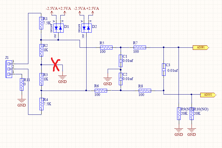
    thank you for your  patience!following picture is the input circuit and code of the ads1282.

    void SPI3_WriteByte(int TxData)
    {
    int i;
    for(i = 0; i < 8; i++)
    {
    if (TxData & 0x80)
    ADS1282_DIN3_1();
    else
    ADS1282_DIN3_0();

    SCK3_1();
    ADS1282_DelaySCLK(7);
    TxData <<= 1;
    SCK3_0();
    ADS1282_DelaySCLK(10);
    }
    }

    unsigned char SPI3_ReadByte(void)
    {
    unsigned char i;
    int read = 0;
    SCK3_0();
    for (i = 0; i < 8; i++)
    {
    SCK3_1();
    if (ADS1282_DOUT3)
    {
    read++;
    }
    ADS1282_DelaySCLK(5);
    SCK3_0();

    ADS1282_DelaySCLK(10);
    read = read<<1;

    }
    read=read>>1;  
    return read;
    }

    int testSPI3()
    {
    unsigned char temp1_read31;
    unsigned char temp1_read32;
    unsigned char temp1_read33;
    unsigned char temp1_read34;     // for 32bit
    unsigned long int temp1_read3_U;
    signed long int temp1_read3_S;

    if(!ADS1282_DRDY3)
    {
    while(!ADS1282_DRDY3);
    temp1_read31 = SPI3_ReadByte();
    temp1_read32 = SPI3_ReadByte();
    temp1_read33 = SPI3_ReadByte();
    temp1_read34 = SPI3_ReadByte();

    temp1_read3_U = 0x00000000;
    temp1_read3_U += temp1_read31;
    temp1_read3_U <<= 8;
    temp1_read3_U += temp1_read32;
    temp1_read3_U <<= 8;
    temp1_read3_U += temp1_read33;
    temp1_read3_U <<= 8;
    temp1_read3_U += temp1_read34;

    temp1_read3_S = temp1_read3_U;
    if( temp1_read3_S & 0x80000000 )
    {
    temp1_read3_S = ~(unsigned long)temp1_read3_S;
    temp1_read3_S &= 0x7fffffff;
    temp1_read3_S += 1;
    temp1_read3_S = -temp1_read3_S;
    }

    printf("ch3 %d\r\n",temp1_read3_S); //double
    }
    return temp1_read3_S;
    }

    the 32bit or 24bit is the same problem.

    there is another matter about the program. you can see i have a read=read>>1;  in read SPI ,i don't know why need this, because read SPI and write SPI are with sck rising edge, if i don't use this statement,the output data will move to right one bit. 

    thank your again!

    best regards

    Kevin

  • Hi Kevin,

    Do you have access to a dedicated SPI peripheral on your microcontroller?
    If you can, I'd suggest using it instead of bit banging here.

    For the erroneous data, it looks like you are trying to convert the ADC result to a two's compliment number, here:

    temp1_read3_S = temp1_read3_U;
    if( temp1_read3_S & 0x80000000 )
    {
    	temp1_read3_S = ~(unsigned long)temp1_read3_S;
    	temp1_read3_S &= 0x7fffffff;
    	temp1_read3_S += 1;
    	temp1_read3_S = -temp1_read3_S;
    }

    This is unnecessary since the conversion result is already in the two's compliment format. All you need to do is concatenate the bytes into the signed data type and remove the duplicate sign bit, like so (note I'm using the signed long instead of the unsigned type here):

    temp1_read3_S = 0x00000000;
    temp1_read3_S += temp1_read31;
    temp1_read3_S <<= 8;
    temp1_read3_S += temp1_read32;
    temp1_read3_S <<= 8;
    temp1_read3_S += temp1_read33;
    temp1_read3_S <<= 8;
    temp1_read3_S += temp1_read34;
    temp1_read3_S >>= 1;            // Make sure right-shift maintains the sign bit

    I think that change might help resolve the issue.

    Regarding the "read = read>>1;" line, that looks like it's necessary because you're shifting the data left at the end of each FOR loop iteration, and you don't need to do the left shift on the very last iteration (because 0x01 << 8 = 0x100).

    Best regards,
    Chris

  • Hi Chris,

    Thanks for you reply, i solved it. 

    Do you have another instruction document about the synchronization, i need sample four signal at same time. But i feel i can't got the point from the ADS1282 specification document page 22-23.

    My Email: peacewyz@163.com

    Thank you again!

    Best regards!

    Kevin

  • Hi Kevin,

    I don't have another other documentation with synchronization instructions. However, if what you're wanting to do is to ensure that all four ADCs are simultaneously sampling, then I would recommend using a single clock source for the ADC's fCLK (master clock) and sending a SYNC command or SYNC HW pulse to all four devices at the same time.

    You might refer to these related E2E threads:

    Let me know if you still have questions.

    Best regards,
    Chris

  • Hi Chris

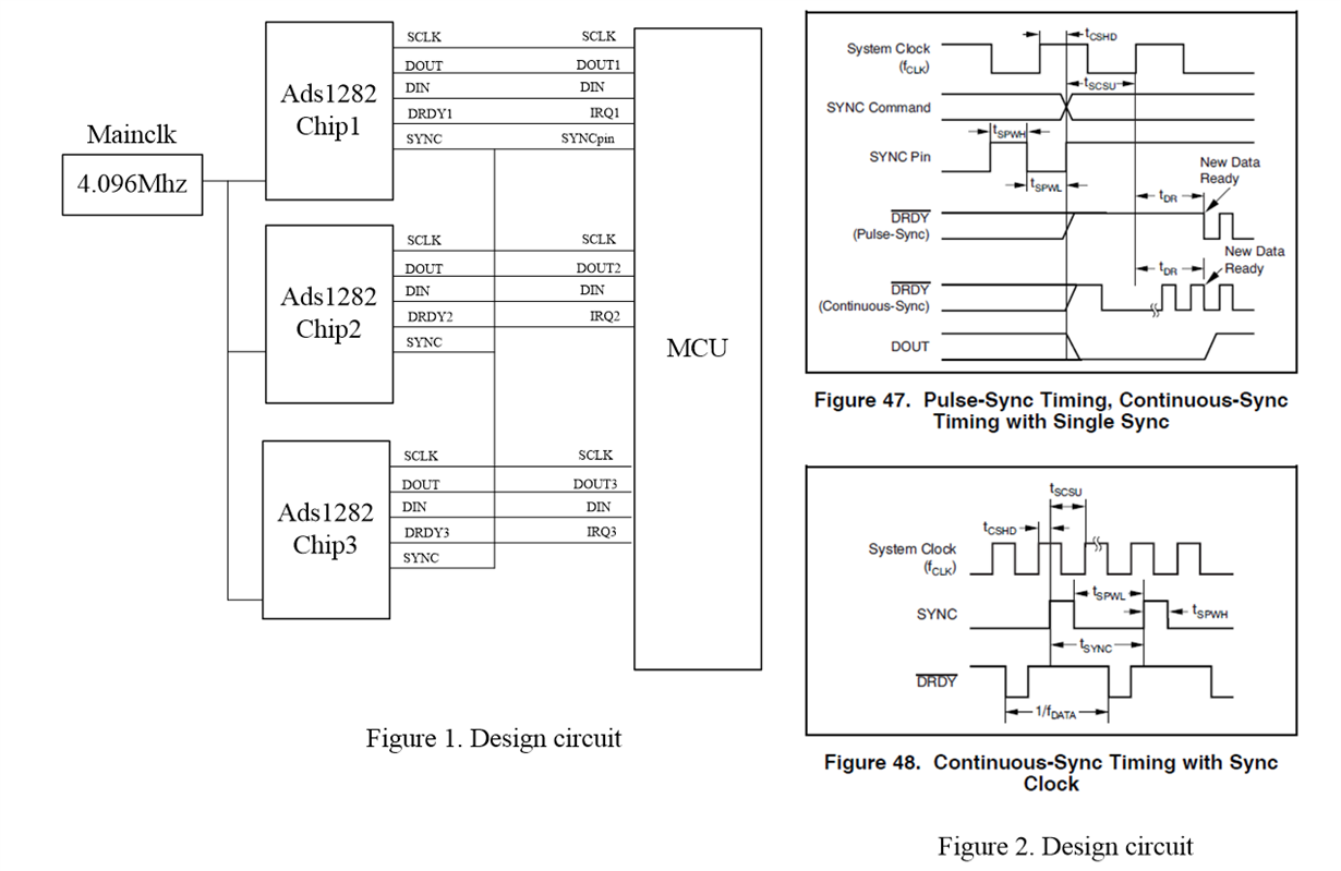
    To disturb you again. I want to get three channel data with ads1282 in sync mode. I design my circuit board like figure 1. Is it correct?

    And I want to program it following the ads1282 datasheet and refer the figure 47 and figure 48, but I don’t realize it. do you have the sequence figure of DOUT1 DOUT2 DOUT3 ,DRDY1 DRDY2 DRDY3 with sync?or can you give me more detail instruction about this?

    PS:  The data output rate of ADS1282 is 500SPS and the frequency of the SYNC signal is 500 Hz

    Best regards!

    Kevin

  • Hi Kevin,

    I don't see any problems with your circuit diagram. You should be okay using 3x different SPI peripherals to communicate with 3x ADS1282s.

    ...One thing to note is that you probably wont need to monitor all 3 DRDY/IRQ signals if the devices are in sync.

    ...The only other suggestion I have would be to source the ADC clocks from the MCU if you intend to use continuous-sync mode of the SYNC GPIO (hardware) signal instead of the SYNC SPI (software) command.


    Do you intend to use pulse-sync mode or continuous-sync mode?

    Since you show an independent clock (independent from the MCU), I might recommend only using the pulse-sync mode and sending the SYNC SPI command (instead of the SYNC GPIO signal). The reason for this is that your SYNC GPIO and CLK signals are not derived from one another and it is very easy for these clocks to get out of sync. When this happens in continuous-sync mode the ADC(s) may re-synchronize unnecessarily. See this related E2E thread: 

    If you use pulse-sync mode and send the SYNC (software) command, you can issue this command at any time to synchronize the ADCs. If you use the SYNC GPIO signal, then please pay attention to the "tCSHD" timing requirement, which requires that the rising edge of the SYNC signal not occur within 10 ns of the rising edge of the CLK signal.


    Best regards,
    Chris