This thread has been locked.

If you have a related question, please click the "Ask a related question" button in the top right corner. The newly created question will be automatically linked to this question.

EEG measurement with ADS1299

Other Parts Discussed in Thread: ADS1299

hi, I'm developing a simple prototype to read EEG signals using the ADS1299 develop KIT.

however, there is a problem with the development process and i have questions regarding this problem.

If only the signal is given to CH 3 as shown below, noise signals are generated in CH4 without a signal.

i want to know why this happens.

thanks.

from Rechard Oh.

  • Hello Rechard,

    Thanks for your post.

    Can please share some additional information? Please include the complete register settings for the ADS1299 and a diagram of the input signal connections.

    Can you quantify how much of the signal from Channel 3 appears on Channel 4? I would suggest using a function generator to input a sine wave of 100mV amplitude and measure the amplitude at the output of Channel 4.

    Regards,

  • Hello Ryan.

    Thank you for responding.

    1. complete register settings for ADS1299.

    ADS1299 RESET

    initialize

    CS LOW

    START PIN LOW

    RESET PIN HIGH

    RESET PIN LOW

    RESET PIN HIGH

    pi1WriteByte(ADS_RESET);

    setup register

    ADS1299_Write(REG_CONFIG1, 0x96);  //default value= 0x96, about Data rate setting

    ADS1299_Write(REG_CONFIG2, 0xC0);

    ADS1299_Write(REG_CONFIG3, 0xFC); // default value= 0xE0, DRL ON= 0xFC

    Input Signal

    ADS1299_Write(REG_CONFIG2, 0xC0); //test signal Not Used.

    ADS1299_Write (REG_CH1SET, 0x60);

    ADS1299_Write (REG_CH2SET, 0x50);

    ADS1299_Write (REG_CH3SET, 0x60);

    ADS1299_Write (REG_CH4SET, 0x60);

    ADS1299_Write (REG_CH5SET, 0x60);

    ADS1299_Write (REG_CH6SET, 0x60);

    ADS1299_Write (REG_CH7SET, 0x60);

    ADS1299_Write (REG_CH8SET, 0x60);

    LOFF Setting

    ADS1299_Write(REG_LOFF,0x00); //Lead_off setting (comp_level,current amplitude,DC/AC)

    ADS1299_Write(REG_CONFIG4, 0x02);  // Lead_off comparator power ON=0x02, OFF=0x00

    ADS1299_Write (REG_LOFF_SENSP, 0xFF);

    ADS1299_Write (REG_LOFF_SENSN, 0xFF);

    ADS1299_Write (REG_LOFF_FLIP, 0x01); // Lead_off curent direction

    RLD Setting

    ADS1299_Write (REG_RLD_SENSP,  0x06); //CH1P RLD

    ADS1299_Write (REG_RLD_SENSN,  0x02); //CH1N RLD

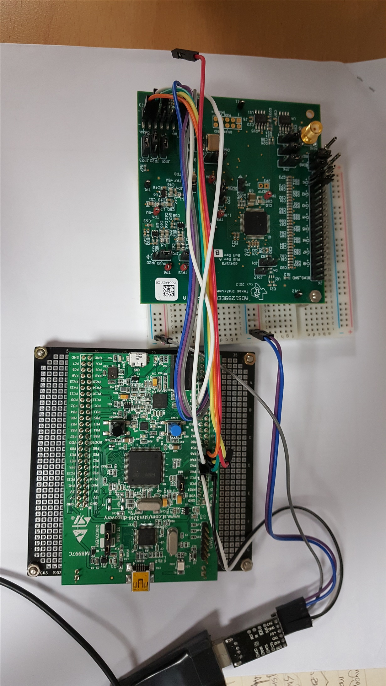
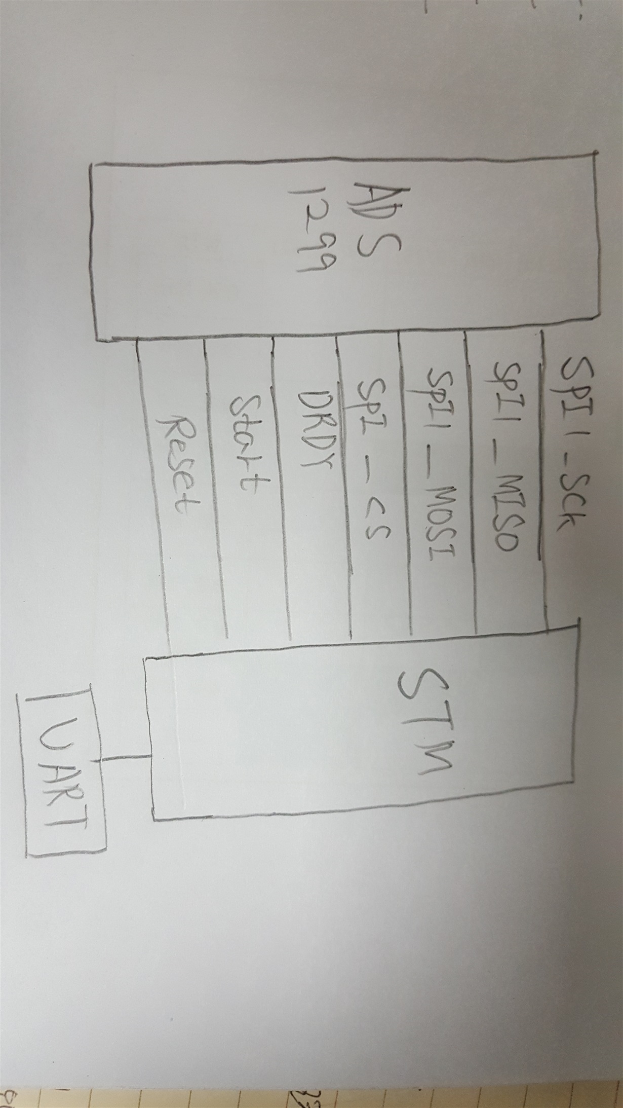
    2. diagram of the input signal connections.

    I will attach a picture.


    I'm sorry. Modify the question.


    Noise does not occur on only 4channels.


    Noise occurs on the channels below of the measured channel.


    For example, if I measure a signal to channel 1 causes noise on channel 2, and if I measure the signal with Channel 2 causes noise on channel 3.

    therefor when measure a signal to channel n causes noise on channel n+1.


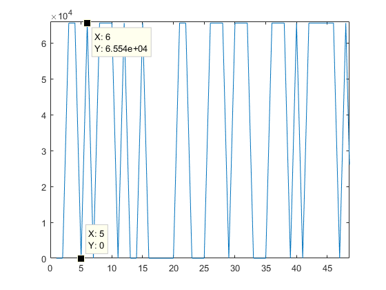
    The picture that you put on the first question is the signal that came out of the filter. I will attach the measured data values without using the filter.


    thanks.  ads1299_output_error.txt

    from Richard Oh


  • Hello Richard,

    What channel was used to produce the data in the attached file? And what was the input signal and register setting for that channel?

    The only values I see are 0 and 65,536. Are you handling the data correctly? Remember that the output of digital filter is in binary two's complement.

    According to your picture, the input pins of every channel appear to be floating. When you evaluate any of our devices, it is important to apply an input signal to the pins so they are not floating. Otherwise, please configure the unused or powered-down channels as an input-short (i.e. MUXn[2:0] = 001).

    Best Regards,