This thread has been locked.

If you have a related question, please click the "Ask a related question" button in the top right corner. The newly created question will be automatically linked to this question.

TLV571: TLV571 with SWPWDN bit set in CR0 will not work (powerdown mode not Normal)

Part Number: TLV571
Other Parts Discussed in Thread: TLC5510A, ADS7884

I have built an oscilloscope using the excellent TLV571 chip.

The results are good using Normal shutdown, however I cannot get Software shutdown to work.

Normal shutdown register settings:

INT OSC FAST, BINARY

CR1: B01010000

SOFTWARE START (D5), EOC (D4),  INTERNAL CLOCK (D3),  NORMAL (D2)

CRO: B00110000

I write CR1 before CRO, using the 1st 3 bits of a bi-directional port (C) to control the read (bit 2), write (bit1) and cs (0) lines:

I wait for the end of conversion line to go high on completion

cli();
PORTC = B00000110; // read high, WR high, CS low
__asm__("nop\n\t");  // wait one machine cycle (at 16 MHz)
                     // yielding a 62.5 ns (nanosecond) delay
PORTC = B00000100; // read high, WR low, CS low
__asm__("nop\n\t");
PORTC = B00000110; // read high, WR high, CS low - transfer data
__asm__("nop\n\t");
  while ((PINC & econ) == 0 ); // wait for econ to go high
sei();

This all works and data can be read using the control port (C) to read data from port (PINA):

PORTC = B00000010; // RD low, WR high, CS low
PORTC = B00000110; // RD high, WR high, CS low
    // wait for econ to go high
    while ((PINC & econ) == 0 );
test = PINA;

This works. (Achieving a data rate of 1189.1 KHz)

However auto reset has a habit of kicking in whilst waiting for the input to trigger, rendering the first 2 data bytes from the TLV571 un-useable.

(The two reading issue is mentioned in the data sheet)

I can partially get round this by continually polling the adc. However this is not ideal.

I have tried changing cr0 to disable auto-shutdown.

B00110100  // cr0  SOFTWARE START (D5), EOC (D4), INTERNAL CLOCK (D3), software powerdown (D2)

The adc then returns a constant value.

I have no idea why.

Any ideas?

David

  • Hi David,

    It mentions in the datasheet that if RD is not present one clock after the conversion it will go into auto power down mode.  Could you try that and see if it helps?

    Mike

  • Thanks for the reply.
    Yes, I read that too and decided that it was unclear whether it meant rd high or rd low.
    So..
    Whilst waiting for a comparator to create an interrupt when the source has reached the trig level and had the correct direction:
    I tried..
    1) holding rd low.
    2) holding rd high

    Both produced the same result- 2 spurious initial data samples when the interrupt fired and data collection started.
    So I resorted to polling for data whilst the interrupt was pending.
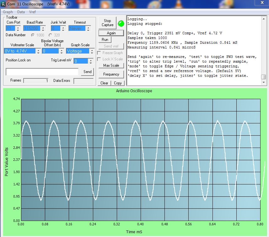
    (The 1st two points are ok as you can see in my screen capture, but not as consistent as those that follow)

    That's why I had a look at the not Normal, powerdown option, which appeared to be adc on until cs low.
    However I could not get any data from the adc when the SWPWDN bit was set.
    Cheers,
    David
  • Hi David,

    What happens if you pulse High to (Low to High) the RD line as shown in Figures 5 and 7.

    Mike
  • Hello Mike,
    Figure 7 is my implementation.
    My setup writes the registers CR0 and CR1, then takes cs low and WR low to high, whilst holding RD high.
    This is the 1st conversion as per the data sheet.
    Subesequently rd always starts high from the previous adc conversion.
    RD is toggled (existing high) to low to high.
    I leave cs low, constantly.
    This all works- 1000 data points at 1.1891 MHz
    As soon as eoc goes high I take the next sample- so no autopowerdown during the 1000 data sampling period.
    What I need to do, is, to prevent auto shutdown whilst waiting for my hardware trigger.

    Have you any thoughts on the the use of the SWPWDN bit? - my disection of the manual has not reveiled anything.

    Cheers,
    David
  • Hi David,

    From my reading of the datasheet is seems like if SWPWDN is 0 (Normal mode) then the part is looking at RD to determine when to shut down.  It will auto power down if RD is not present one clock after conversion.  Could you try this, as soon as EOC goes high pulse the RD pin to low and back to high and see if that helps? 

    The other option is if SWPWDN is 1 (Powerdown mode) the power down is controlled directly by pulling CS to DVDD.

    I have not been able to find the area of the datasheet where it says that the first conversion after power down is bad.  Could you point it out to me?

    Mike

  • Hi Mike,

    as I said, "As soon as eoc goes high I take the next sample"

    That is my polling solution.

    The problem with SWPWDN = 1 is that the TLV571 always returns a fixed number when it is set.

    (not necessarily the same number after disconnecting the power)

    I cannot find a reference in the datasheet to suggest what else must be done when SWPWDN is set-

    There may well be a fault in the internal coding of the chip, or perhaps you have access to alternative details?

    Re the invalid reading: cf  power up and initialization on page 12:

    Cheers,

    David

  • Hi David,

    I also am not able to answer your questions just from reading the datasheet. I have asked some engineers that have supported this part in the past to see if they know the answer. I will let you know if they have any answers.

    Mike
  • Hi David,

    One of the engineers that worked with part many years ago said the proper way to use the software shutdown is to set SWPWDN = 1 and then bring CS high. We have not been able to figure out why you get a fixed number when it is set. You are getting that value when you have SWPWDN = 1 and CS = 0? Unfortunately we don't have any access to the internal properties of this chip because it was designed so long ago.

    Mike
  • Hello Mike,

    Firstly I appreciate your diligence in the pursuit of this problem.

    I have tried variations in the CS state during the setup of CR0, without success.

    (Rather like fishing without a map of the riverbed or knowing which fish to target!)

    This works for normal mode:

    //setup data port to output on port "PORTA"

    //setup control line c0-c2 output, c0 = CS, c1 = WR, c2 =RD on port "PORTC"

    byte cr1 = B01010000;
    PORTA = cr1;

    cli(); // disable interupts
    PORTC = B110; // read high, WR high, CS low
    __asm__("nop\n\t");  // wait one machine cycle (at 16 MHz)  yielding a 62.5 ns (nanosecond) delay
    PORTC = B100; // read high, WR low, CS low
    __asm__("nop\n\t");
    PORTC = B110; // read high, WR high, CS low - transfer data
    __asm__("nop\n\t");
      while ((PINC & econ) == 0 ); // wait for econ to go high
    sei(); // enable interrupts

    cr0 = B00110000;

    PORTA = cr0;

    cli();
    PORTC = B110; // read high, WR high, CS low
    __asm__("nop\n\t");

    PORTC = B100; // read high, WR low, CS low
    __asm__("nop\n\t");
    PORTC = B110; // read high, WR high, CS low - transfer data
    __asm__("nop\n\t");
      while ((PINC & econ) == 0 ); // wait for econ to go high
    sei();

    DDRA = B00000000; Data port now input
    test = PINA; // get data off port

    Serial.print(F("Test read "));
      for(byte i = 0; i < 10; i++) {
      PORTC = B00000010; // RD low, WR high, CS low
      PORTC = B00000110; // RD high, WR high, CS low
      // wait for econ to go high
        while ((PINC & econ) == 0 );
      test = PINA;
      Serial.print(" "); Serial.print(test);
      }

    The output with a square wave as source:

    Test read  9 9 9 5 248 249 251 9 9 8

    Works!

    With cr0 = B00110100;

    Output:

    Test read  249 249 249 249 249 249 249 249 249 249

    Fixed eroneous data

    I tried

    1) sending all control lines high after the write cycle

    2) Toggling cs high during the write cycle:

    cli();
    PORTC = B110; // read high, WR high, CS low
    __asm__("nop\n\t");

    PORTC = B100; // read high, WR low, CS low
    __asm__("nop\n\t");
    PORTC = B111; // read high, WR high, CS high - transfer data
    __asm__("nop\n\t");
      while ((PINC & econ) == 0 ); // wait for econ to go high
    sei();

    3) keeping CS high during the data read

    The result: (B11111001)

    Test read  249 249 249 249 249 249 249 249 249 249

    Any suggestions for a specific control line flow structure would be greatly appreciated.

    Regards,

    David

  • Hi David,

    From the description you have of the code and results it seems like there are 2 different types of power down. It looks like when 1 is written to D2 of CR0 the part goes into an immediate power down and will not give back results. It looks like this power down mode lasts until a 0 is written to D2 of CR0.
    The second type of power down is when D2 of CR0 is set to 0. There are two versions of power down in this mode. One is to make a reading and not have RD present one clock cycle after the conversion. The other way is to pull CS to DVdd.
    It could be possible to test this by looking at the supply current and trying each of the ways of going into power down. Normal supply current is between 4 to 7 mA depending on supply and clock. As you try each of the ways you should see the current go down.

    Mike
  • Hello Mike,

    I agree with your description. This was the conclusion I had come to when I posted the question.

    I am not in a position to disect my circuit  board to measure the supply current.

    As I detailed above, there is no method of preventing autopowerdown, other than..

    cycling the RD line.

    Setting D2 in CR0 is a pointless option- I suspect the repeated number returned from the ADC data lines after D2=1 is simply the last value written to the data line when D2 is set.

    I will therefore move on.

    Is there a parallel, 5v reference adc  with at least 1.2 Msps and a more recent pedigree?

    I am looking at the TLC5510A with 20Msps and a maximum reference of 4V - not ideal.

    Regards,

    David

  • Hi David,

    The TLC5510A is the closest device that I could also find to your requirements.  If you were able to go to a SPI interface instead of parallel, that makes available some other choices like the ADS7884.

    Mike