This thread has been locked.

If you have a related question, please click the "Ask a related question" button in the top right corner. The newly created question will be automatically linked to this question.

ADS1248: k-type thermocouple programming/parameter

Part Number: ADS1248

Hello,

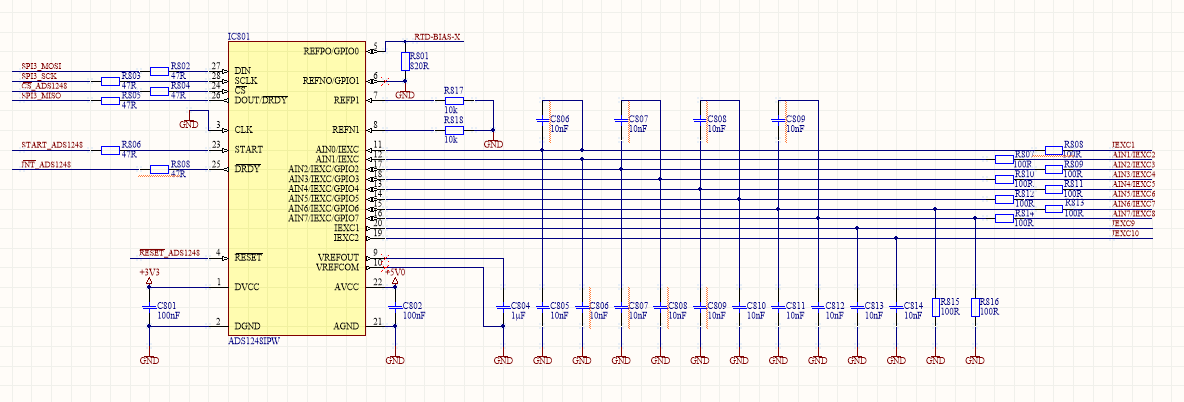
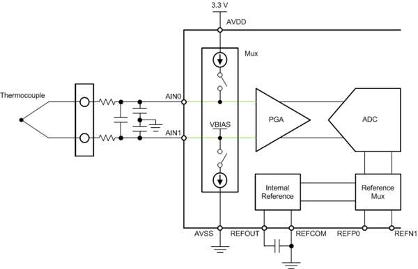
we are working on an application given the following design:

The general spi communication is working (verified with oscilloscope). We can write/read registers and get data results via RDATA command.

We need support for

a) finding the correct register settings given the attached schematics

b) converting the digital result back to thermocouple voltage.

To a) Currently we tried the following register settings for reading the first channel

            SetRegisterValue(MUX0, MUX_SP2_AIN0 | MUX_SN2_AIN1);    // channel 1
            SetRegisterValue(MUX1, REFSELT1_ON| VREFCON1_ON);        // ADS Reference on Intern, Internal Reference on
            SetRegisterValue(IDAC0, IMAG2_1000);                    // IDCA0 = 1000µA
            SetRegisterValue(IDAC1, I1DIR_AIN1);                    // IDAC1 = AIN1
            SetRegisterValue(VBIAS, VBIAS_RESET);                   // no bias
            SetRegisterValue(SYS0, PGA2_32);                        // pga 32 default sps 5

To b) From data sheet topic 9.5.2 Data Format 1 LSB = (2 × VREF / Gain) / 2^24 = +FS / 2^23 Is the following equation the correct way to get the thermocouple voltage?

raw_value = RDATA_RESULT();

lsb = (2 * 2.048 / 32) / 16777216;

voltage =  raw_value * lsb

Thank you for any help on this.

Greetings,

Daniel

  • Daniel,


    I think your setup should be able to make thermocouple measurements, and all that is required is that the ADC is set up for that measurement. For the measurement, the inputs simply measure the thermocouple voltage, and compare the voltage to a known reference. The thermocouple does not require excitation. All that is required is that the thermocouple is biased within the range of the PGA (near the mid-supply point, especially if the PGA is in higher gains).

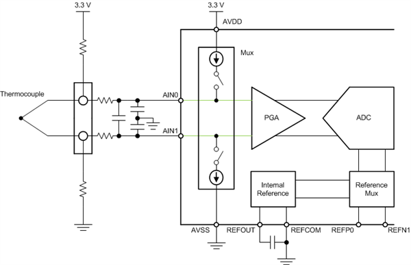
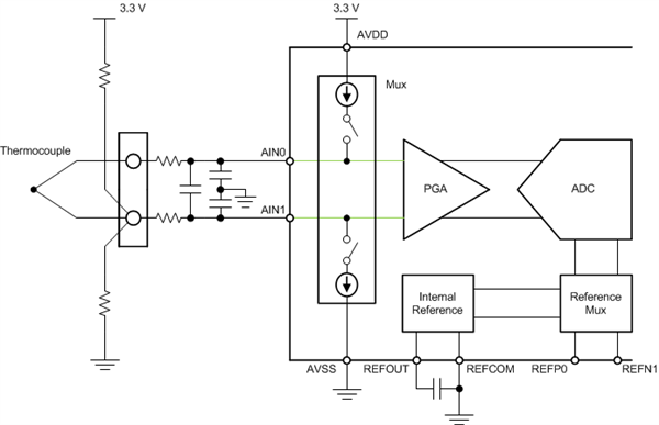
    There are a few different ways to bias a thermocouple. Often, resistors are used to bias the thermocouple. Two common ways are like this:


    and this:


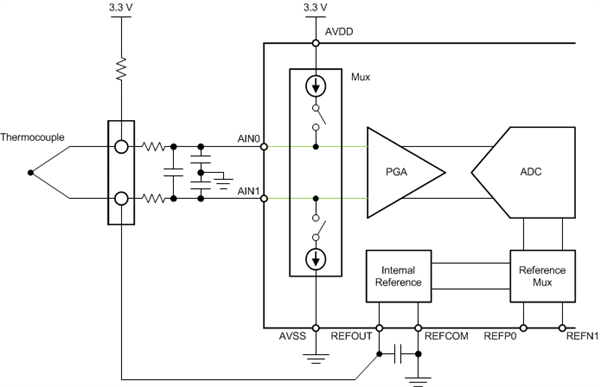
    You can even bias the thermocouple with the internal reference voltage:


    However, since you already have the design schematic, you can use the VBIAS in the multiplexer and attach it to one of the thermocouple leads like this:


    To set up the register to properly measure the thermocouple. This is what you need to set up. Attach the thermocouple to AIN0/AIN1.

    1. Select the mux so that AINP is set to AIN0 and AINN is set to AIN1.
    2. Connect VBIAS to AIN1. This will attach the thermocouple's negative lead to a mid-supply bias point.
    3. Enable the internal reference to be always on and use the internal reference for the ADC.
    4. Set the PGA to 32 (presuming you want to use a gain of 32, for the input range) and set the data rate.
    5. The IDACs are not used, so you will want to disable them and disconnected.
    To calculate the voltage from the ADC data, this is the equation you would use:

    Thermocouple Voltage = (ADC output * 2.048V)  / (2^23 * 32)


    Joseph Wu

  • Daniel,


    One other thing that I wanted to point out is that if you want to connect the inputs to AIN6 and AIN7, you'll need to R815 and R816. The 100Ω resistors will be not be compatible with the measurement.


    Joseph Wu
  • Hello Joseph,

    thank you for your help. We got it working.

    If i need further support i'll com back.

    Greezt,

    Daniel