This thread has been locked.

If you have a related question, please click the "Ask a related question" button in the top right corner. The newly created question will be automatically linked to this question.

ADS1146: Register write failure

Part Number: ADS1146
Other Parts Discussed in Thread: ADS1246

Hi

A write to the system control register (or any other register in the device) fails to update. I can however read the initialized values as per datasheet and they match! What setting can block a write to the configuration registers?

Perhaps my initialization sequence is wrong?

1 - Set START = 1, set RESET = 0;

2 - wait 20ms

3 - Set START = 1, set RESET = 1;

4 - wait 20ms //omitted this delay makes no difference

5 - send the command SDATAC //this will only take effect after the next READY signal

6 - wait for the READY signal

7 - Read the 16 bit answer to clear DOUT

8 - Read all the registers in one sweep (11) //this is just to see how they compare to the datasheet.

BCS = 0x01

VBIAS = 0x00

MUX1 = 0x00

SYS0 = 0x00

OFC0 = 0x00

OFC1 = 0x00

OFC2 = 0x00

FSC0 = 0x00

FSC1 = 0x00

FSC2 = 0x40

ID = 0x72

9 - write Control system register = 0x05 //set speed at 160SPS

10 - wait 40 microseconds

11 - read all 11 registers in one sweep to compare -> All the registers stay the same, the control register does not update!

Please advice.

Phlip

  • Philip,


    There shouldn't be anything that can block a write to the register as long as the timing requirements are met. However, there are still things to look at in the communication.

    Are you able to get a scope photo for the SPI lines? If you have a four channel scope, grab a look at SCLK, DIN, DOUT, and /CS. It would help to see all waveforms to check on timing. If you have a logic analyzer, pick up /DRDY also.

    What is the SCLK frequency? If you have SPI reads and writes set up separately, you might have the wrong SPI flavor setup. Do you have /CS set up to stay low through the entire write process? I'd also check to see if you don't have some errant reset in your setup that returns your registers to the default setting.

    Regardless, see if you can get a scope photo of the communications and post the result back.


    Joseph Wu
  • Hi,

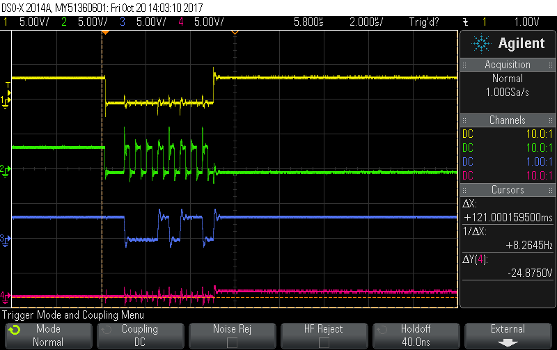
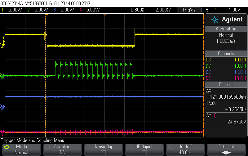
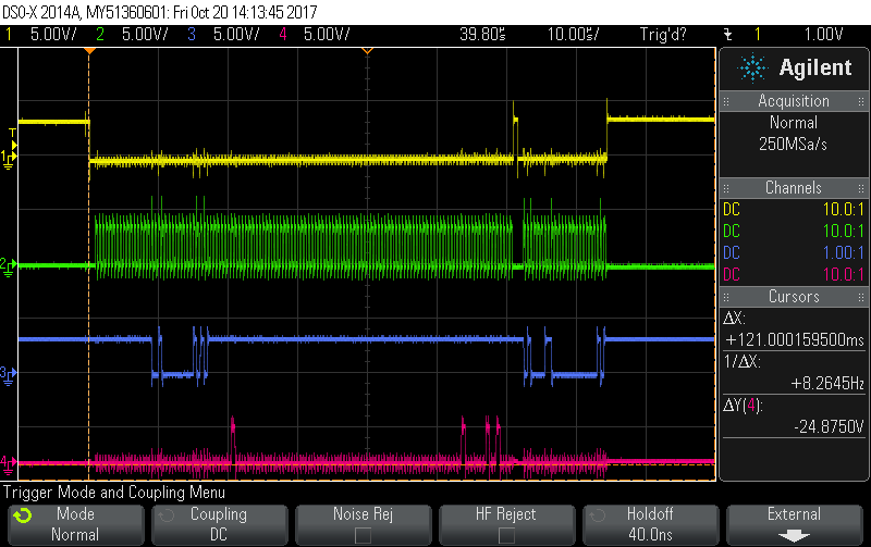
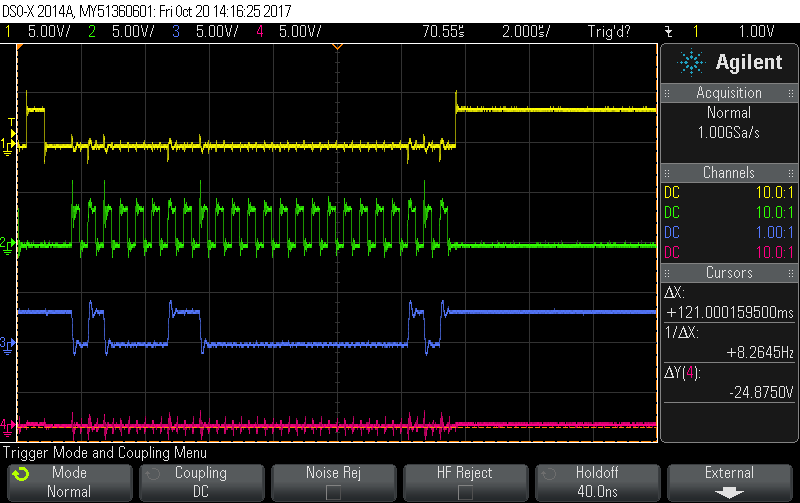
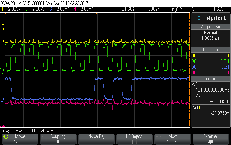
    please find scope captures of the SPI lines below. The speed of the SPI is 1MHz. All channels is set to 5V/div and the time scale 2 uS/div or 10uS/div. The top (yellow) waveform is the /CS, the second (Green) is the Clock (my SPI is setup to delay the clock after /CS, hence the gap before the clock appear), the third (blue) is the DI (MOSI) and bottom (Red) is the DOUT (MISO).

    "stop continuous read" command:

    Get result after Ready signal:

    Read registers before write command, write command follows immediately:

    Zoomed in on write command that follows read registers:

    This write command (above) seems to have no effect.

    The waveform is a bit noisy, although it should not be the reason not to write a value to the registers...

    Phlip

  • Philip,

    First, make sure that the START pin is high, so that the device is enabled. I believe that if the START pin is low, you may still read from the device (including the registers) but you may not write to the device.

    Second, make sure that the SPI communications is clean. Noise on the SCLK in particular can cause the device to advance the SCLK count when an SCLK wasn't sent by the master. If you're just working with one board, a cap on SCLK might help out. I don't think this is your problem, but it might head off problems later.

    Let me know if the START pin is the problem. It it isn't we'll look into other possibilities.

    Joseph Wu

  • Philip,


    Also, check to make sure that you're not in sleep mode. Sleep mode and a low START pin are functionally similar.


    Joseph Wu
  • Joseph,

    I did check the START pin as well as the READY pin. The start pin does stay high after my initial reset. The READY pin stays low and pulses high continually after every conversion is done. This means that it is running and not in power down mode?

    A 180 pF capacitor on the SPI lines clears up the noise. As you expected this does not seem to be the problem.

    I, however did find pulses on the RESET line that sometimes dip as low as 2.5V where the digital VCC is 3.3V. Can this reset the device? The pulses correspond to the DI line of the SPI, every rising edge dips the RESET line and the falling edges lets the RESET line spike. I could not find any short between the RESET line and any SPI line, all of them is in the high kilo ohms. When I disconnect the DI line, the noise on the RESET line disappears of cause.

    The lines does not run alongside each other on the PCB, neither do they cross. Any advice?

    Phlip
  • Philip,


    Yes, when the /DRDY pin is low, but has repeated pulses, it means that the device is not in power down mode. The repeated pulses should be at the data rate of the device, indicating when each new conversion completes.

    As for the /RESET line, it's possible that the scope isn't showing the full picture. Depending on the resolution and bandwidth of the scope, you may miss a fast transient spike on /RESET line. I'd try adding another cap on /RESET to try to keep it from drooping.

    At this point it looks like the device is partially responding, with DOUT responding to the SCLK. Since you're not able to write to the register, I'd also look carefully at the DIN line. I'd make sure that signal is solid going from whatever master you're using to the pin of the device. Is it possible that the DIN pin has been damaged from some sort of ESD or overvoltage event?


    Joseph Wu

  • Joseph,

    I did replace the capacitor on the RESET line with different values to see how the results compare. There is improvement but did not resolve the issue so, I suspect a ESD damage on the DI pin to be the problem as you suggested. I have to wait for new parts unfortunately but, will upload new results as soon as I can.

    Phlip
  • Joseph,

    I replaced the device and find similar results. Here is a shot at the RESET (RED) line in comparison to the DI line (Blue) while the clock (Green) and /CS line (Yellow) also show some noise. The glitches on the RESET line dips down to 2.8V! Filter caps does not seem to filter out these spikes. If I remove the RESET line and short it to VCC, the glitches only get smaller instead of disappear. This tells me there is a ground issue but all the necessary pins are properly grounded.

    This bugs me really, why should digital inputs be that sensitive? Any ideas?

    Phlip

  • Philip,


    There are a few things that I can think of that might help. First, assuming that you have a unipolar supply, how do you have AVSS and DGND connected? As you mentioned there may be some ground loop that's causing problems with the DGND connection to ground. Normally, we recommend a single ground plane to reduce ground loop voltage problems. If you feel the need to separate analog and digital grounds, they can be laid out separately and connected under the device.

    Second, do you use any inductors or ferrites in your supply path? Inductors may try to smooth out the current in the lines, but in digital supplies, you can make the voltage spiking worse. Digital lines will be clocked and with a certain amount of spiking digital current, the L(dI/dt) may cause large disruptions on the voltage lines.

    Third, if you have a the option, series resistance in the SPI lines may help slow down the signal even more. If you look at the ADS1246EVM, you can see how we've set up the circuit. However don't really use anything except for a single series resistor on SCLK. The digital lines are generally robust. We use a Schmitt trigger on the inputs.

    If you have a schematic and layout, you can post them here if you're able. Another thing to try would be to either get the ADS1246EVM board or solder an ADS1246 onto a generic TSSOP board and air-wiring it to your controller just to test it.


    Joseph Wu
  • Hi Joseph

    I use a unipolar supply and use a ground plane with both AVSS and DGND connected.

    I do not use inductor or ferrites on the board at all.

    I do use series resistors in all of the digital lines, at first only 47 ohm but did increase it to 120 ohm and use 100pF capacitors connected to ground.

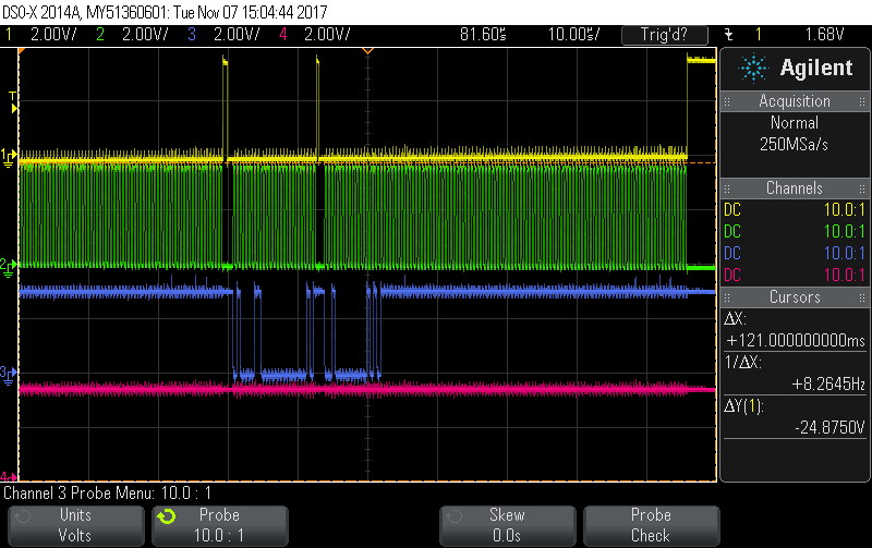
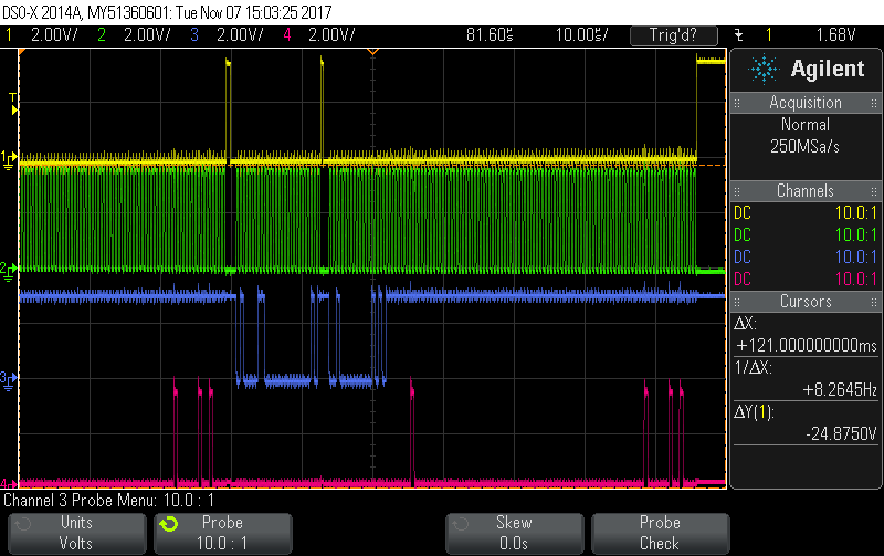
    I did managed to clear out the RESET line it seems, scope captures below.

    Yellow = /CS; Green = clock; Blue = DI; Red = RESET

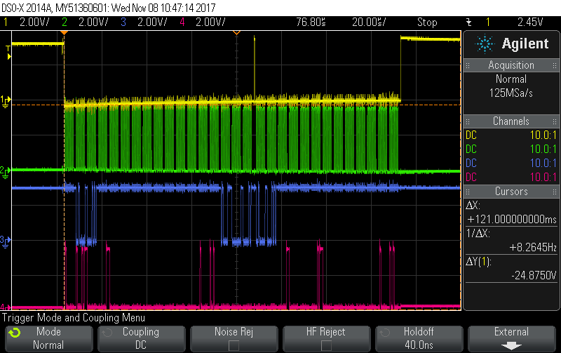
    Below the capture of the DO instead of the RESET

    The result stay the same after the write operation, no registers changed? I think we can eliminate a reset option now.

    Phlip

  • Philip,

    I don't see anything wrong in the actual byte transactions. I've taken the last plot and expanded it out to look at it carefully:

    I wasn't sure about the last byte, but it's probably ok (I think that you'd previously reported 72h).

    However, I was a bit concerned about the timing. If you look at Figure 1 and Section 7.6 in the datasheet, they show the timing requirements for communicating with the device. In particular, I'm not sure you're giving enough time for the time from the last SCLK to the rising edge of /CS (7 tCLK - about 2 us) or for the /CS pulse duration (5 tCLK - about 1.5us). I think your scope shot shows 10us/div, so I think you're short on both.

    I would review all the timing and make sure that everything else is ok. Then make the changes and see if they help. I'm reasonably sure that violating the SCLK to /CS timing could result in a failed write.

    Joseph Wu

  • Philip,


    If this fails to get a good write to the register, could you please post the schematic and layout? It might help to review it. I think you've been able to write SDATAC to the device, but if that was unsuccessful, I'd check the DIN line all the way from the master to the device.


    Joseph Wu
  • Hi Joseph

    This time delay before the /CS line rise again was the main problem I think. Now it works properly. Thank you.

    The below capture shows the extra bits on the second read (Red waveform) after the write, indicating a successful write.

    Best regards.

    Phlip

  • Philip,

    I'm glad you got it working. Timing problems can be hard to identify if you don't have the right scope shot. Your previous post had just enough information to help.

    Go ahead and verify the rest of the timing. It's hard to tell but in your last post, the /CS duration looked less than the 1.5us minimum. Regardless, good luck with your project and let me know if you have any questions.

    Joseph Wu