This thread has been locked.

If you have a related question, please click the "Ask a related question" button in the top right corner. The newly created question will be automatically linked to this question.

ADS1292R: Response from read register command

Part Number: ADS1292R

Hello all,

I am trying to interface ADS1292R with STM32F429 ARM processor via SPI. Circuit for ADS1292R is the same as ADS1292RECG-FE.

I am trying to read just ID register, so I am sending first opcode byte 20h and second opode byte 00h. Response is 73h ( which is correct ) but also 02h ( which is not correct ). I connected logic analyzer and I am seeing the same thing. Where is that 02h coming from?

EDIT: I found out that 02h is data from CONFIG1 register. However I am still not sure why is ADS1292R sending data from two registers when I am using command to read just one register. Also if I send command to read two registers ( example from datasheet ), ADS1292R sends data from three registers. Is that a bug or am I doing something wrong? Also here is example of writing to register CONFIG1 and then requesting data from two registers, starting from register CONFIG1. It can be seen that ADS1292R sends data from three registers CONFIG1, CONFIG2 and LOFF.

Thanks in advance for any help,
Josip

  • Hello Josip,

    Thanks for your interest in our ADS1292R!

    Can you share an image that shows the entire SPI sequence, including the commands you're sending and the data that is clocked out? Please share this for each of the two images you posted above. If you'd like, I believe you can also save the capture to a file and attach it to your post. I use the same Saleae Logic software, so I could open it on my end and review it more closely.

    If you are only sending 0x20 0x00 (read one register, starting at 00h), then I'm not sure what to expect from the device if additional SCLKs are sent. That is the correct command sequence. I'll ask a designer to see if this is expected behavior.

    Best Regards,

  • Hello Ryan,

    thank you for response.

    Here is capture of both pictures.

    capture.zip

    EDIT: Also I have one more important issue now.

    I want to read data continously but after some time /DRDY just stays high.

    Can you verify my steps?

    1. Issue SDATAC 

    2. Send RESET

    3. Toggle CS

    4. Set START pin to 0

    5. Activate SPI interface, /CS=0. (CPOL=0, CPHA=1, 1MHz)

    6. Write registers to next configuration

    CONFIG1: 0x00

    CONFIG2: 0xA3

    LOFF: 0x10

    CH1SET: 0x15

    CH2SET: 0x80

    RLDSENS: 0x00

    LOFFSENS: 0x00

    LOFFSTAT: 0x00

    RESP1: 0x02

    RESP2: 0x03

    GPIO: 0x03

    7. Check that all registers were written. (they are written correctly)

    8. Set START pin to 1

    9. Send RDATAC.  (I have checked that /DRDY toggle continously after this step)

    10. Read /DRDY pin and read data. (here after some time /DRDY just goes high)

    Do you have some idea, what could be wrong?

    Best Regards

  • Hi Josip,

    I don't see anything wrong with the commands you're sending. Just a note on the SCLK - your comments mentioned SCLK = 1MHz, but it looks like the frequency is actually 250kHz.

    You really should only send as many SCLKs as required by the command you're sending and the data you're reading. So if you're reading 2 registers, you only need two bytes for the command and two bytes for the register data. Still - let me try to find out why DOUT shows more than just 0x00 when extra SCLKs are sent.

    In your startup procedure, there's no reason to set START = 0 when setting up the register configurations. START controls the ADC conversions, which can be left free-running during SPI transactions. You only need to send SDATAC before sending SPI commands.

    If the master clock (CLK) is running continuously and START = 1, the /DRDY should not stop pulsing. /DRDY may idle high for awhile if you change the registers because this resets the digital filter. After the settling time has passed, /DRDY should resume pulsing low at the set data rate.

    Best Regards,
  • Hi Ryan,

    thank you for response.

    I played with SCLK in a process of debugging and I forgot about that, so thats why it is 250kHz.

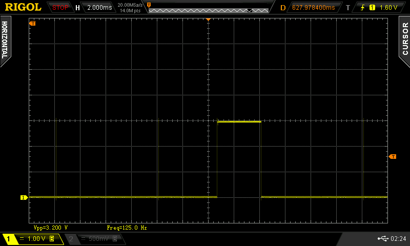
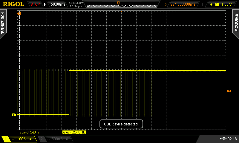
    As for /DRDY going high, I think that part of my reading of /DRDY pin and SPI communication might be a problem but I am still not sure. Here you can see pictures from scope of /DRDY pin during single read and during continous reading in RDATAC mode. You can see that after a while, in continous reading, /DRDY pin goes high ( and it doesnt resume pulsing low at the set data rate)

    Single read

    Continous reading

    Best regards and thank you for help,

    Josip Puskar

  • Hi Josip,

    Any progress on this issue?

    Is there any way that you can disconnect the /DRDY pin from other circuitry? Header pins/test points are fine so you can continue probing, but I'm wondering if something external in you system (i.e. the MCU) is loading the /DRDY pin somehow and holding it high.

    Best Regards,