This thread has been locked.

If you have a related question, please click the "Ask a related question" button in the top right corner. The newly created question will be automatically linked to this question.

ADS1292R: Respiration and ECG Data Rate Problem

Part Number: ADS1292R
Other Parts Discussed in Thread: TM4C123GH6PZ

Hi, 

I've continued Laura Cupic's work on interfacing ADS1292R with TM4C123GH6PZ microcontroller:

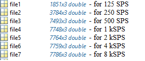
I've succesfully interface microcontroller with ADS1292R, but the problem occurs when the Data Rate is changed comparing from 125SPS to 8kSPS. 

ADS1292R register values:

CONFIG2   -> 0xA0 (reference buffer enabled)

LOFF          -> 0x10 (lead-off disabled)

CH1SET     -> 0x60 (CH1 enabled, gain 12)

CH2SET     -> 0x60 (CH2 enabled, gain 12)

RLDSENS  -> 0x2F (chop freq=fmod/16, RLD enabled, RLD inputs from CH1 and CH2)

LOFFSENS-> 0x00 (default)

RESP1       -> 0xEA (resp mod/demod enabled, phase 112.5, internal clock)

RESP2       -> 0x03 (32kHz freq, internal reference voltage)

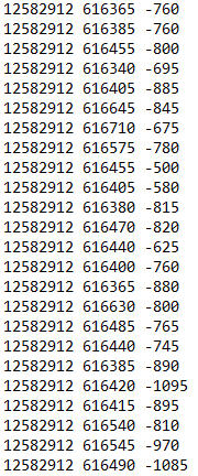
Signal acquisition: simulator -> ADS1292R -> TM4C123GH6PZ (SPI, SCLK = 1MHz ) -> Laptop (UART, Baud Rate=115200)

Respiration signal and ECG are acquired from simulator (LA, RA, LL and RL), Respiration rate is set to 15 per minute (0.25 Hz), so for the Data Rate of 125SPS, 1000 samples equals to 2 periods of respiration signal as shown on the image. Math is correct for 250SPS (2000 samples), 500SPS (4000 samples) but higher than that number of samples sticks to around 4200 for any higher data rate. Same is for CH2 (ECG).

Questions:

1)  Why is number of samples locked for frequencies higher than 500SPS?

2) Why higher frequencies have more noise?

  • Hello Tin,

    Thank you for your interest in the ADS1292R and welcome to the forums!

    1) The number of samples is not locked. Where are you saving this data to? Perhaps it is reaching its limit.
    1a) Page 32. of the datasheet covers continuous conversion mode. Is it possible that your start pin is being toggled low or the stop code is being transmitted?
    1b) Another test to try would be to let a lower sampling rate test run for longer to confirm that it the device stops capturing data after 4200 samples.

    2) There is more noise at higher sampling rates because as the sampling rate increases the oversampling rate decreases. The CONFIG2 register shows the relationship between oversampling ratio and sampling rate. Table 4. shows the relationship between sampling rate and noise-free bits. As the sampling rate increases, the number of output bits that are compromised by noise increases as well.
  • Hello Alexander,

    Thank you for the quick response and welcoming me to the forums.

    1) I've wrongly expressed what the actual problem was. In the graphs on attached picture, I've cut manually number of samples to show exactly 2 periods od respiration signal. I'm able to get more samples if I transfer data for longer period of time. For example samples used for the attached picture were cut down from data around 15 seconds long. This is plotted data for 125SPS data rate I have recorded from respiration simulator for around 15 sec from where I've cut manually 2 periods for the picture in prevous post:

    Problem is with data rates higher than 500SPS.

    Variables 'file1' to 'file7' are from workspace in Matlab derived from function dlmread that reads data from .txt files. 'file1' is for 125SPS, 'file2' for 250SPS, etc. For every data rate, data is recored around 15 sec, so the number of rows in the variables 'file' that represents number of samples has to double if the data rate is doubled. 

    15s/8ms = 1875 samples for 125SPS, 15s/4ms=3750 samples for 250SPS, etc.

    That is true for data rates 125, 250 and 500SPS. But for higher data rates, for example 2kSPS: 15s/1ms=15000 samples and I get 7764 samples. It seems that max data rate I can get from device is around 516SPS according to number of recorded samples.

    2) Thank you for pointing me to Table 4. The number of compromised bits seems to increase as the higher data rate is chosen no matter to problem 1).

    I hope I've clarified what the actual problem is.

  • Happy to help and thank you for clarifying!

    My current thought is that this is a data storage buffer problem. Perhaps wherever you are storing data to is filling up faster than it can empty. I would suggest looking further into this. What software are you using to collect the data?

    The next step is to take a look at your digital SPI pins:

    1) Are you in RDATAC or RDATA mode? This will help us understand if your samples are being corrupted or if they are being missed.

    2) Probe your SPI pins to make sure that when DRDY toggles that there is enough time for CS to go low and SCLK to send 72 clocks (24 status + 2channels * 24 bits) before DRDY signals that another sample is available. Your previous post said that your SCLK is running at 1MHz which should be plenty fast to take the data, but take a look to make sure that your routine doesn't have an issue that is causing you to corrupt or miss samples.
  • I'm also suspecting that it is data storage problem.

    1)I'm using RDATAC mode

    These are my main.c and ADS1292R.c

    main.cpp

    3554.ADS1292R.c
    #include <stdint.h>
    #include <stdbool.h>
    #include "inc/tm4c123gh6pz.h"
    #include "inc/hw_memmap.h"
    #include "inc/hw_ssi.h"
    #include "inc/hw_types.h"
    #include "driverlib/gpio.h"
    #include "driverlib/pin_map.h"
    #include "driverlib/sysctl.h"
    #include "driverlib/uart.h"
    #include "driverlib/ssi.h"
    #include "ADS1292R.h"
    
    void Delay_ms(uint32_t t){
    	t = 26667 * t;      // 1ms/(3*12.5ns) = 26666.6667
    	SysCtlDelay(t);     // delay t[ms]
    }
    
    void Reset()  {       
    	GPIOPinWrite(GPIO_PORTA_BASE, GPIO_PIN_6, GPIO_PIN_6);   //PWDN/RESET high  (OFF)
    	Delay_ms(2);  
    	GPIOPinWrite(GPIO_PORTA_BASE, GPIO_PIN_6, 0x00);         //PWDN/RESET low   (ON)
    	Delay_ms(2);  
    	GPIOPinWrite(GPIO_PORTA_BASE, GPIO_PIN_6, GPIO_PIN_6);   //PWDN/RESET high  (OFF)
    	Delay_ms(2);  
    }
    
    void ADS1292R_Init()  { 
      Reset();
    //  Delay_ms(100);
    //  Send_Command(STOP);
    //	Delay_ms(100);
    //  Send_Command(START); 
    //	Delay_ms(20);
      Send_Command(STOP);								
      Delay_ms(10); 
      Send_Command(SDATAC);
      Delay_ms(10); 
    	
      Write_Register(CONFIG1, 0x05); 		// 500 SPS, read data continuous
      Delay_ms(1);
      Write_Register(CONFIG2, 0xA0);	  // lead-off comparators off, ref.buffer enabled, test signal disabled
      Delay_ms(1);
      Write_Register(LOFF, 0x10);		    // lead-off disabled
      Delay_ms(1);
      Write_Register(CH1SET, 0x60);	    // channel 1 enabled, gain 12, input is normal electrode
      Delay_ms(1);
      Write_Register(CH2SET, 0x60);	    // channel 2 enabled, gain 12, input is normal electrode
      Delay_ms(1);
      Write_Register(RLDSENS, 0x2F);	  // chop freq = fmod/16, RLD enabled, RLD inputs from channel 1 and 2
      Delay_ms(1);
      Write_Register(LOFFSENS, 0x00);		// LOFFSENS: default (disabled)
      Delay_ms(1);															   	
      Write_Register(RESP1, 0xEA);	   	// CMOD/DEMOD turned ON, phase 112.5, internal clock for respiration
      Delay_ms(1);
      Write_Register(RESP2, 0x03);		  // calibration on, respiration freq 32kHz, internal ref.voltage
    	Delay_ms(1);                      
    	Write_Register(GPIO, 0x00);       // GPIO -> OUTPUT
    	Delay_ms(1);
    	
    //	Send_Command(OFFSETCAL);    // offset calibration
    //	Delay_ms(100);
    	Send_Command(START);		    // start conversion
      Delay_ms(2);
    	Send_Command(RDATAC);	      // enable read data continuous mode (must be disabled while configuring registers)
      Delay_ms(2);
    }
    
    void Send_Command(unsigned char command)   {
    	uint32_t dummyRec;
    	
    	GPIOPinWrite(GPIO_PORTA_BASE, GPIO_PIN_0, 0x00);        // CS low (ON)
    	Delay_ms(1);
    	GPIOPinWrite(GPIO_PORTA_BASE, GPIO_PIN_0, GPIO_PIN_0);  // CS high (OFF)
    	Delay_ms(1);
    	GPIOPinWrite(GPIO_PORTA_BASE, GPIO_PIN_0, 0x00);        // CS low (ON)
    	Delay_ms(1);
    	
    	SSIDataPut(SSI0_BASE, command);        // send command opcode
    	while(SSIBusy(SSI0_BASE));	           // wait for data to be sent
    	SSIDataGet(SSI0_BASE, &dummyRec);      // receive dummy data
    	
    	Delay_ms(1);
    	GPIOPinWrite(GPIO_PORTA_BASE, GPIO_PIN_0, GPIO_PIN_0);  // CS OFF
    }
    
    void Write_Register(unsigned char reg_address, unsigned char data)  {
      switch (reg_address) {    // to be sure we don't change reserved bits in registers
    		case CONFIG1: {
    			data = data & 0x87;
          break;		}
    	  case CONFIG2:  {
    			data = data & 0xFB;
    	    data |= 0x80; 
    		  break; }
    		case LOFF:  {
    			data = data & 0xFD;
    	    data |= 0x10; 
    		  break; }
    		case LOFFSENS:  {
    			data = data & 0x3F; 
    		  break; }
    		case LOFFSTAT:  {
    			data = data & 0x5F; 
    		  break; }
    		case RESP1:  {
    			data |= 0x02; 
    		  break; }
    		case RESP2:  {
    			data = data & 0x87;
    	    data |= 0x01; 
    		  break; }
    		case GPIO:  {
    			data = data & 0x0F; 
    		  break; }
    		default: {
    			break; }		
    		}
      uint8_t addr_OR_WREG = reg_address | WREG;   // 0b0000.00rr OR 0b0100.0000
    	// to read, we need to send 2 bytes:
    	//  1. 0b010r rrrr, (r rrrr represents register_adress, WREG = 0x40)
    	//  2. 0b000n nnnn (n nnnn represents numbers of registers to read)
    	uint32_t dummyRec;	
    	
    	GPIOPinWrite(GPIO_PORTA_BASE, GPIO_PIN_0, GPIO_PIN_0); // CS high (OFF)
      Delay_ms(1);
    	GPIOPinWrite(GPIO_PORTA_BASE, GPIO_PIN_0, 0x00);	     // CS low (ON)
      Delay_ms(1);
    	
    	SSIDataPut(SSI0_BASE, addr_OR_WREG);  // WREG + reg. adress
    	while(SSIBusy(SSI0_BASE));
    	SSIDataGet(SSI0_BASE, &dummyRec);     // get dummy data
    	
    	SSIDataPut(SSI0_BASE, 0x00);          // number of registers to write, 0x00 == 1
    	while(SSIBusy(SSI0_BASE));
    	SSIDataGet(SSI0_BASE, &dummyRec);     // get dummy data to flush reciever FIFO
    	
    	SSIDataPut(SSI0_BASE, data);          // send value to write into register
    	while(SSIBusy(SSI0_BASE));
    	SSIDataGet(SSI0_BASE, &dummyRec);
    	
      Delay_ms(1);
    	GPIOPinWrite(GPIO_PORTA_BASE, GPIO_PIN_0, GPIO_PIN_0); // CS high (OFF)
    }
    
    //uint32_t Read_Register(unsigned char reg_address)  {
    //  uint32_t dummyRec;
    //	uint32_t readData;                      // data that has been read from register will be saved here
    //  uint8_t addr_OR_RREG = reg_address | RREG; // 0b0000.00rr OR 0b0010.0000
    //  
    //	GPIOPinWrite(GPIO_PORTA_BASE, GPIO_PIN_0, GPIO_PIN_0);  // CS high (OFF)
    //  Delay_ms(1);
    //	GPIOPinWrite(GPIO_PORTA_BASE, GPIO_PIN_0, 0x00);        // CS low (ON)
    //  Delay_ms(1);
    //	
    //	SSIDataPut(SSI0_BASE, addr_OR_RREG);     // RREG + register adress
    //	while(SSIBusy(SSI0_BASE));
    //	SSIDataGet(SSI0_BASE, &dummyRec);
    //	
    //	SSIDataPut(SSI0_BASE, 0x00);           // number of registers to read
    //	while(SSIBusy(SSI0_BASE));
    //	SSIDataGet(SSI0_BASE, &dummyRec);
    //	
    //	SSIDataPut(SSI0_BASE, 0xFF);           // send dummy data
    //	while(SSIBusy(SSI0_BASE));
    //	SSIDataGet(SSI0_BASE, &readData);      // get register value
    //  
    //  Delay_ms(1);
    //	GPIOPinWrite(GPIO_PORTA_BASE, GPIO_PIN_0, GPIO_PIN_0);  // CS high (OFF)
    //	return readData;
    //}
    
    
    char* Read_Data()  {  // 
    	uint32_t rec_8Bits;
    	static char data_array[10];
    	int i;
       
      GPIOPinWrite(GPIO_PORTA_BASE, GPIO_PIN_0, 0x00);       //  CS low (ON)
    	SysCtlDelay(1);                                // delay 300*37.5ns=11.25us                      
    	for (i = 0; i < 9; i++)  {
    		SSIDataPut(SSI0_BASE, 0xFF);                   // send dummy data
    		while(SSIBusy(SSI0_BASE));                     // flush the transimit FIFO
    		SSIDataGet(SSI0_BASE, &rec_8Bits);             // recieve data into recieved8Bits
    		data_array[i] = rec_8Bits;                     // store data into array
    	}
    	SysCtlDelay(1);                                // delay 300*37.5ns=11.25ms                      
    	GPIOPinWrite(GPIO_PORTA_BASE, GPIO_PIN_0, GPIO_PIN_0); // CS high (OFF)
    	
    	return data_array;
    }


    For data transmission I'm using UART2 pins on TM4C123GH6PZ connected to UART-USB bridge and for writing to .txt file Putty configured for 115200 baud rate.

    Could you verify if my code is causing this problem?

    Thanks

  • Hello Tin,

    I hope you had a nice weekend.

    Have you had any luck tracing where the data is being saved to and any possible bottlenecks?

    I took a quick look at your code and didn't find anything in particular that looked incorrect. However, I did notice that for the RESP2 register, Calibration is off whereas the comment indicates that it should be on.
  • Hello,

    I found the problem, it was UART baud rate. I've increased it to 921600 bps and managed to get 10000 samples (recording for 10 sec) at data rate of 1kSPS. The datasheet of UART to USB Brdige states that the max baud rate is 921200 bps. I tried higher data rates and the new problem occurs. For example at data rate of 2kSPS first 6 seconds I'm getting the correct data:

    And after 6 seconds I'm getting this:

    Next I'll try recording data to flash memory and then transfering it through UART to PC.

    As of calibration, I was testing it and didn't correct the comments.

    Thanks for your advices.

  • Hi Tin,

    I'm glad that you were able to increase the number of samples taken!

    This looks to me like your samples are being truncated/replaced as the baud rates get increasingly out of sync.

    Using RDATAC vs RDATA will have an effect on how this lack of sync is represented.

    Happy to help! Let me know how your next test goes.