This thread has been locked.

If you have a related question, please click the "Ask a related question" button in the top right corner. The newly created question will be automatically linked to this question.

DAC5571: DAC5571 unwanted reset of output voltage

Part Number: DAC5571

Hi everybody,

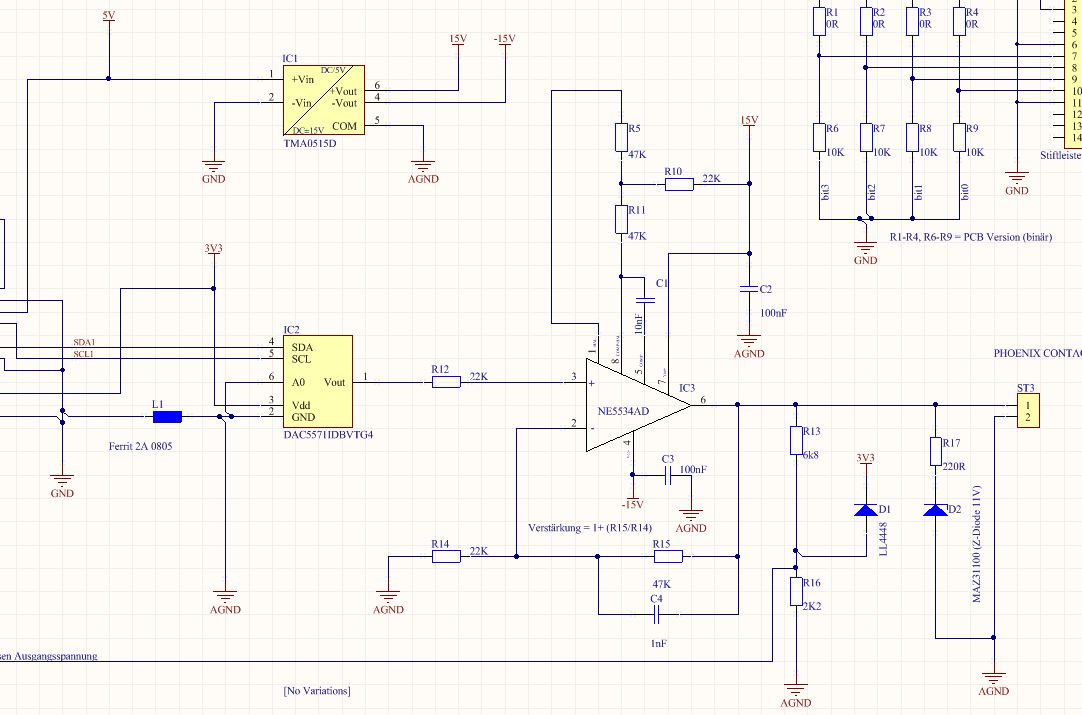
i have a question concerning the DAC "DAC5571".

I´m using this chip in my circuit and most of the times it works without problems, but

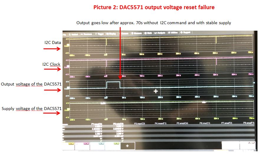
Sometimes the output voltage is reset to 0V without receiving any I2C command.

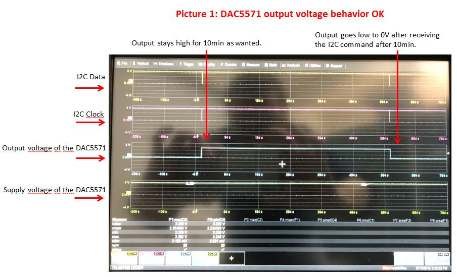
In my application the output voltage should stay for 10min. After 10min an I2C command

from my microcontroller will set the output voltage to 0V. This works most of the times,

but sometimes the output voltage is reset to 0V long before the 10min have passed without receiving any I2C command.

I have attached two oscilloscope pictures where the behavior can be seen.

Picture1 shows the expected behavior, Picture2 shows the faulty behavior

Does anyone have an idea what the reason for this behavior could be?

Any help is appreciated.

Kind regards

Kai

  • Hi Kai,

    Welcome to E2E and thank you for your query. I am looking into your issue. I will get back on this by tomorrow. In the meanwhile, could you please confirm whether this issue is board specific or happens across multiple boards? If it is board specific, please reverify the assembly.

    Regards,
    Uttam Sahu
    Applications Engineer, Precision DACs
  • Hi Uttam,

    thank you for your reply.

    This issue happens accross multiple boards. One customer complaint about that. Then we examined the problem
    and found the mentioned behavior.
    On the board is also DC/DC Converter +5V to +-15V. This DCDC converter produced some noise of about 100kHz that also coupled on the supply voltage of the DAC. The supply voltage fluctuated due to the noise between 2,7V and 3,5V volts with 100kHz, so I thought this is the reason for the issue, but now I have removed that DC/DC converter completely and the phenomenon remains.
    I must admit that the layout of that little board is not perfect, thats the reason why I have also observed the supply voltage of the DAC.
    After removing the DAC there are still little peaks on the supply voltage, letting the supply voltage fluctuate between 3,24V and 3,35V. Do you think that is still a problem? The supply voltage comes from an underlying bigger board. The underlying board have a switch mode power supply that produces 5V. A line regulator creates then 3.3V for the rest of the logic (also for the DAC). The two boards are connected through two 14pin SMD headers.

    If you need more information let me know.

    Thanks for your efforts and help!

    Kind regards
    Kai Becker
  • Hi Kai,

    Thank you for the information. Looks like the device is going through a power-on reset cycle due to the glitches in the power supply. This will make the DAC output to zero.

    Could you please share the schematics? If you don't want to share it in public, you can send it to my mail. Please send me a friend request and I can share my email ID as a private message.

    I want to check the decoupling arrangement for the DAC. We might be able to play with the de-caps to get rid of the problem.

    Regards,
    Uttam
  • Hi Uttam,

    thanks for your anwer.

    Yes that was also my thought, that the DAC is going through a power-on reset cycle. This seems to be the obvious reason, but I thought that

    the power supply that I have now (without DAC) is good enough for the DAC.

    Of course the datasheet mentions that the power supply should be very "clean".

    Here is the shematic of the DAC 5571

    And here is the power supply for the DAC5571 coming from the mainboard

    If you need more information please let me know.

    Kind regards

    Kai

  • Hi Kai,

    While your schematics has good amount of decoupling near the switching supply, I couldn't find any of them near the DAC. This can be one of the strong reasons of the failure you are observing. You have ferrite beads on the VDD and GND path and no decoupling cap on the DAC side. This can cause large spikes across the ferrite beads whenever there is a switching current. This might lead the Power-on Reset circuit to get activated in turn creating a DAC reset.

    The best way to use the decoupling caps in your design is to go with a new board layout. However, you can try soldering de-caps on the DAC pins and check.

    Hope that answers your question.

    Regards,
    Uttam
  • Hi Uttam

    thanks for your efforts and help.

    You are certainly right with everything you said. I will first try to improve the situation on one board so that

    the customer that complained about the behavior can use our device. Then I will start the layout of the

    new PCB.

    Thanks you very much again for your help!

    Kind regards

    Kai