This thread has been locked.

If you have a related question, please click the "Ask a related question" button in the top right corner. The newly created question will be automatically linked to this question.

DAC8740H: hart communication design

Part Number: DAC8740H
Other Parts Discussed in Thread: DAC161S997, , DAC8771, DAC8750, DAC8760

Dear sir,madam

Please find the attachment pdf, and let me know is there any changes required in design.

Application.

1) we are designing 2-wire loop power 4-20mA output with HART.

2) we are using DAC161s997 to convert digital signal into analog output.

3)We are communicate DAC8740H with DAC161S997, Please checked and let me know is that correct circuit design.TWO WIRE 4-20mA WITH HART.PDF

  • Hi,

    I reviewed your schematic and have a few comments:

    1. The HART input capacitance should be 6.8nF based on the datasheet recommendation. This is C30 on your schematic and has a value of 0.22uF.

    2. C27 and C26 are large capacitors across LOOP-P and LOOP-M. These will attenuate the HART signal, especially the 1uF capacitor. In HART compliance testing there is a specific input impedance test requirement across the loop terminals. These large capacitors will create a very low input impedance. I would recommend using a lower capacitance value across the loop terminals.

    Thanks,
    Garrett
  • Thank you very much for quick response Garrett.

    other all schematic is right?

    Also we want to design hart communicator to read hart signal on line and connect with PC. can you suggest me design?

  • Hi,

    I didn't notice any other issues with the schematic.

    A secondary device will just consist of the HART modem (MODIN) AC coupled to Loop+ and Loop- and a microcontroller to handle the demodulated data. The microcontroller is also responsible for interfacing with the PC.

    Thanks,
    Garrett
  • Dear Garrett,

    Please find attachment of three wire 4-20mA with Hart.

    We are confuse in below attachment. can you tell me how to connect DAC161s99 and DAC8740 in three wire 4-20 mA system. where we connect mod IN signal and loop+ and loop- signal.

    threewire hart.pdf

  • Hi,

    The DAC161S997 is a 2-wire current loop device and is designed to be powered from the loop current. A 3-wire transmitter cannot be achieved with this device.

    For a single channel 16-bit 3-wire current transmitter design I would recommend looking into DAC8771, DAC8760, or DAC8750. DAC8771 and DAC8760 have voltage and current outputs while DAC8750 has only a current output. Coupling the HART signal should be straight forward with these devices.

    Thanks,
    Garrett
  • Thanks you very much. We design new schematic using DAC8760 and DAC8740. but we confuse in HART and DAC connection diagram. Please checked below schematic and rectify us.3-wire_4-20mA Output Section.pdf

  • Rohit,

    Let's split this topic between transmit and receive paths.

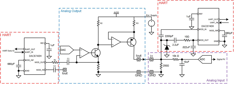
    For the transmit path you need to consider which output ranges of DAC8760 IOUT you will use. As is noted in both the datasheet and separate Application Note, the HART-IN pin is only active for the 4-20mA output range. If any other range is used, either the CAP2 pin or ISET-R paths need to be used for coupling the output HART FSK waveform onto the current output. Full details are in the Application Note: http://www.ti.com/lit/an/slaa572/slaa572.pdf.

    Currently your schematic has the ouput HART FSK coupled onto the HART-IN pin, so I would assume you plan to use the 4-20mA range, but it's worth double-checking as I pointed out. Meanwhile, you have the receive HART path connected to ISET-R and CAP2, which as I mentioned are actually the alternative paths for the transmit FSK depending on the ranges in use. You will not see incoming HART FSK data on these pins.

    Garrett wrote a blog about the structure of a HART-enabled PLC analog input module, which would pair up with something like DAC8760, which you can read here:

    The main point is that the AI module is going to couple it's output FSK signals onto the shunt resistor used to measure the 4-20mA and to receive the HART FSK data. That means the HART receive path for your AO module needs to be the same node. We illustrated this in a tech-day presentation we have shared this year, the image is below. I hope this helps.