A related question is a question created from another question. When the related question is created, it will be automatically linked to the original question.
If you have a related question, please click the "Ask a related question" button in the top right corner. The newly created question will be automatically linked to this question.
First, let's think about what calibration will do. There is an ideal transfer function and the actual ADS1118 transfer function. The difference between the two linear outputs will be the starting point (offset) and slope (gain). So you would correct for offset and gain. If you consider the equation of a line where Y = mX + b, b is the offset and m is the slope. The calibration values adjust the codes by adjusting the offset and correcting the slope to get the approximation of the ideal.
To do this you first determine the offset (which can be either positive or negative even with the single-ended measurement as the ADS1118 will always measure differentially or AINP relative to AINN). Apply a 0V input to the ADC and use the value returned from the ADC as the offset. This value should be subtracted from all remaining conversions and this should be done prior to any gain correction. Next apply a voltage close to full-scale. The ratio of this value to the ideal value is difference in gain (slope). Use these factors to determine the corrected code by subtracting the offset and multiplying by the slope.
I don't fully understand what information you are looking for. Initially you show a schematic snippet of the ADS1118-Q1, and now you are asking about an evaluation kit. When you say "How to Calibration" what exact information are you looking to have explained?
First of all you need to determine if calibration is even necessary. Many applications do not require a calibration. If a calibration is necessary, then either the calibration can be done using the conversion result as it relates to the device reference (which is a voltage and the calibration is with respect to voltage) or the calibration can be adjusted to some other unit such as pressure, weight, temperature, etc. which would relate to the sensor (or calibration of the sensor).
To keep things simple, let's look at calibration for a voltage as the ADS1118 returns a code relative to a full-scale range in volts.
The above figure shows an offset. The Ideal line shows that for any given input Voltage, a specific conversion Code output from ADC will be given. The Offset Error line shows that even though the result is similar, there is a shift in codes between the two lines. This is the offset, and once the value of the offset is known it can be subtracted out of the conversion result returned. To find the offset you need to first apply a short at the inputs which now becomes 0V. The expected code is 0. If the conversion code returned is not 0, then there is an offset. To correct the offset you would subtract that non-zero code from all other conversion results. Note that I have shown a positive offset, but the offset can be either positive of negative. The offset correction should always be done first prior to any other correction.
The above figure shows gain error after the offset correction. Note how gain error effects the result more as the input approaches full-scale. If the input voltage is small relative to the full-scale range, then gain correction may not be necessary. To correct for gain error, you determine the difference of the Ideal to the Gain Error as a ratio. So what you are going to determine is what value can you multiply times the conversion result to get to the result to follow the Ideal line.
I do not know which board you have. Can you tell me a specific part number or attach a picture of the board? We have no boards labeled EVK, so I need to know which board is being used. If you are using a 3rd party board (not produced by TI), we will not have any specific code as a starting point. As far as any documentation regarding calibration for the ADS1118, we don't have anything specific to that device, but it would follow exactly as I have stated in this thread.
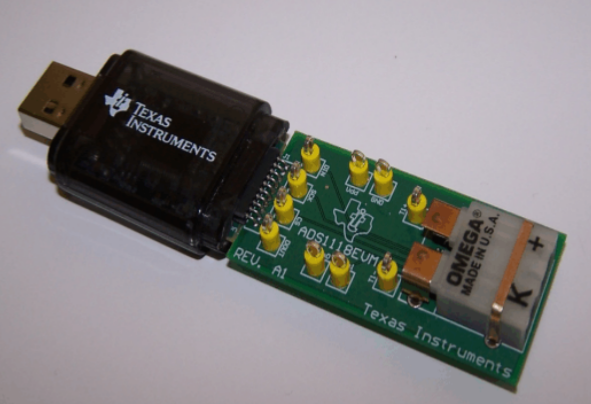
First, if you are using the ADS1118EVM with this board:
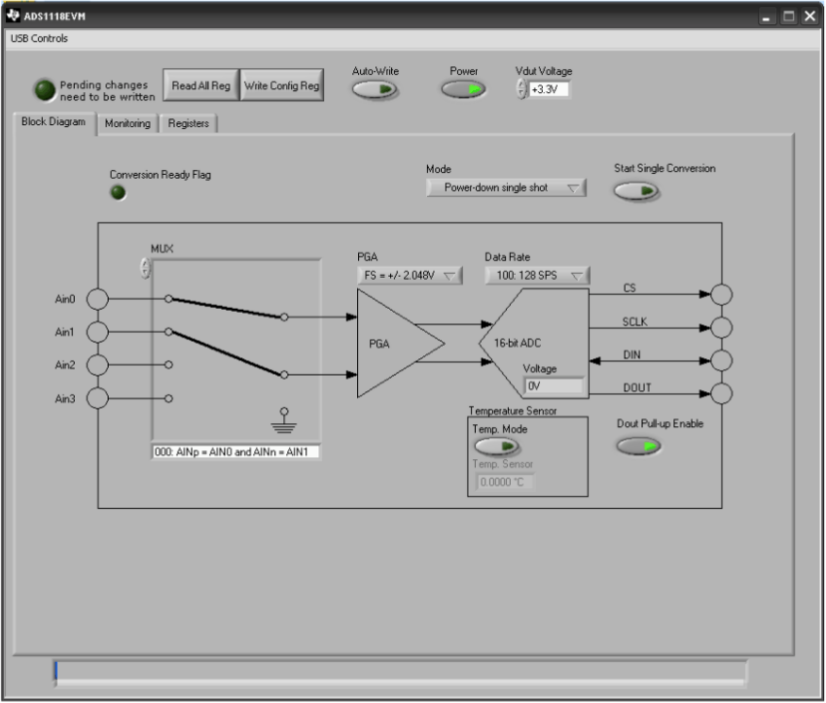
and this software:
then there is no simple way to calibrate the board. The ADS1118EVM was designed as a demo, and the software is designed to only capture the data as a temperature. Also, the ADS1118 has no calibration command like some of the other precision devices that we make.
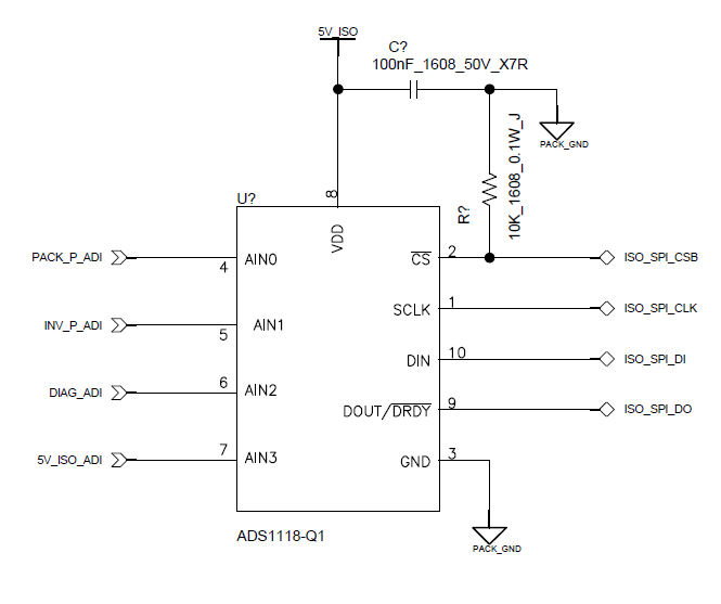
However, if there is a measurement similar to that shown in your first schematic, then you can manually do a form of calibration. This would require attaching a known input to the system and then make calculations to adjust for the error that you see. Below, I'll give a basic outline of what you want to do.
For calibration, you want to do two things:
- Remove the offset
- Remove the gain error
First you want to set the device in the mode of operation that you will use it. Set the gain (input range), input channel, and the data rate.
1. Remove the offset. I would short the input to ground to measure 0V. This will give a measure of the offset. This should give an output code of 0000h. However if it does not, then this would be an offset error. This data should be recorded as the offset error and subtracted from future measurements.
2. Remove the gain error. After removing the offset, you need to make a measurement of the gain error and multiply a scale factor to remove the error. First use a known source that is close to positive full scale of the measurement. If you are using the ±2.048V, then you will need a source that is +2.0V (do not use a +2.048V source if the source happens to be larger than the input range, then you cannot measure the gain error).
Measure the input and an subtract out the offset code. This will give the ADC measurement for the input value. If you are using a 2V source for a ±2.048V range, then the output code should be 7D00h (32000d). However, any error from this value is a gain error. To remove gain error you take the ideal code, divide by this measurement and multiply future values to this value. For example if you get an output code (with this 2.0V measurement) of 7E00h, then the ADC has a gain error that makes the measurement high. To compensate for the gain error you would need to multiply future measurements with 7D00h/7E00h (32000/32256). This is a scale factor of 0.99206, and should be multiplied to data after the offset is removed.
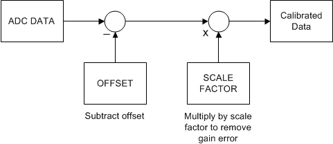
In short, each data taken from the ADC should be modified with the following to get calibrated data:
Unless you are changing gains, you can probably use the same calibration values for each channel. If you are changing gains, you need to make measurements for each gain range separately (for both offset and gain error).
Hopefully this explains the method of calibrating the ADS1118. If you have any other questions, please post back.