This thread has been locked.

If you have a related question, please click the "Ask a related question" button in the top right corner. The newly created question will be automatically linked to this question.

DAC8534: DAC Latch-Up

Part Number: DAC8534

Hi,

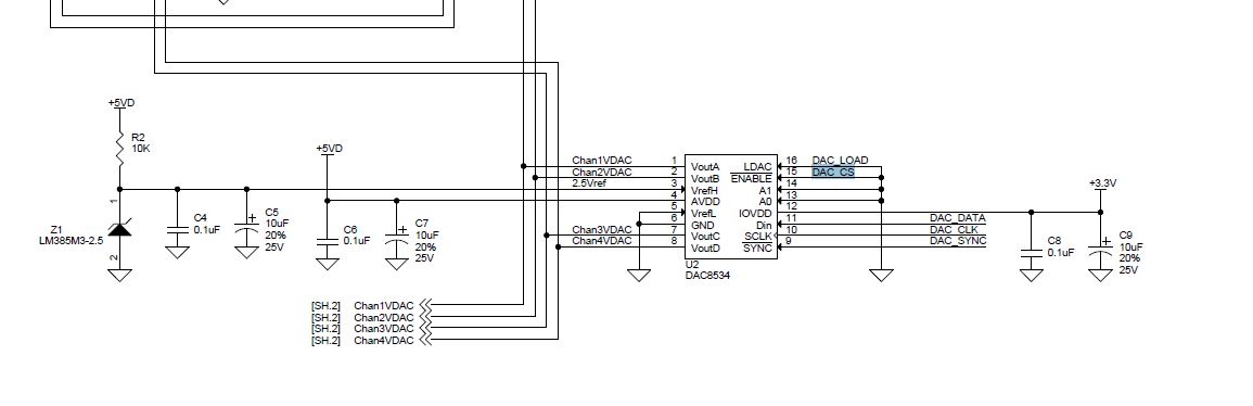
The outputs of DAC8534 sometimes get into a latch up state. The outputs won't change unless the board is power cycled.
Is there a way to reset the DAC to an initial state and to restore the outputs without having to power cycle the system? I don't
see any reset register in the datasheet! 

Thanks 

  • Hi Bob,

    Welcome to E2E and thank you for your query. Could you please provide us the test conditions? Schematics, programming sequence etc.

    Regards,
    Uttam Sahu
    Applications Engineer, Precision DACs
  • Hi Uttam,

    Attached is the schematic of DAC8534. We apply an ESD voltage of around a few hundred volts to CHAN2VDAC return and the DACs output would lock up. We are not able to change the DAC's output value unless we power cycle the board. Is there a way to reset the DAC to release it from lock up state without having to power cycle the board?

    Thanks,

    Bob

  • Hi Bob,

    The DAC is tested for ESD per JEDEC standard. Does your system require a device level ESD testing? If you can provide details on the ESD level and shape you are applying, I will be able to tell you whether they are beyond what is specified for the device or not.

    As far as I understand, ESD specs need to be met at a system level and the voltages are much beyond what can be handled by a device. Hence, external protection circuits at IO's will be required.

    Regards,
    Uttam
  • Hi Uttam,

    No we don't require device level ESD testing but we do ESD testing on all the I/Os. We apply ESD voltage of a few hundred volts to 4KV using
    1 pulse per second. Attached is the picture of ESD waveform. 

    Attached is also the schematic of protection circuits for the I/Os. I hate to repeat myself, but is there a way to reset the DAC8534 to an initial state
    once its outputs are locked up. The only way to get it out of the latch up state is to power cycle the board.

    Thanks,

    Bob


  • Bob,

    The only reset included in this particular device is the POR which occurs based on power supply ramps at power up - therefore the only way to issue a reset is through toggling power.

    The only thing we can offer you on this device is to continue examining the root cause of why the latch up state occurs and attempt to implement circuitry to prevent that. If you want to continue that discussion, please let us know.

    In general I would also offer some additional commentary that may be helpful for you regardless of the path you choose going forward. Be wary that reset pins and/or reset commands in firmware are not all created equal (not just for TI - this seems to present industry-wide). What I mean to say is that sometimes these are "shallow" resets which revert the user-visible register contents to their default value. This contrasts to a "deep" reset which would reset input shift registers, reload OTP / trim values, and basically issue an overall complete re-initialization of the entire device core. In many cases the "deep" reset is required to remedy a latch-up issue - assuming the latch-up isn't actually based in the analog domain where some SCR internally may have tripped. If the SCR were the root cause, though, depending on the current limit of your supply, you could see more catastrophic damage to the device.

    Hope this helps.

  • Hi Kevin,

    Would you be able to propose a circuit that could prevent the DAC latch-up issue. We are already providing some protection for analog output and its return signal. Specifically, we use TVS devices on all outputs and utilize PCB spark gaps for surge protection.

    Thanks,
    Bob
  • Hi Bob,

    The protection circuit you have used looks fine except a few points:

    1. You have used TRIAC's instead of TVS diodes. TRIAC's have a very high trigger voltage and the DAC might be getting the impact before that
    2. There might be secondary arcs from your shield ground to the DAC ground depending on how they overlap each other in your system
    3. I see that DAC Chan 2 and Chan 4 don't have capacitors near the connector. This may be one cause in case you see different results with different channels

    In order to protect the DAC outputs from direct or secondary discharge, I would suggest putting another level of protection with TVS diodes or zeners close to the DAC pins. The ferrite beads will make sure the initial impact is taken by the TVS diode near the connector. The TVS diodes near the DAC will take the secondary impact and then the residual will be taken by the internal ESD diodes.

    Hope that answers.

    Regards,
    Uttam
  • Hi Uttam,

    Thank you for your suggestions. We will try to implement your recommendations when we do a new design.
    As for our existing design, could we use an external signal conditioner, like an analog passive isolator,
    to protect DAC?

    Best Regards,

    Bob 

  • Hi Bob,

    I am not able to visualize your system and where you apply the ESD. Nonetheless, if there is an isolator between the discharge point and the DAC output lines, it would work. But analog isolators can be inaccurate.

    Another method that I have seen being effective is using a ferrite core on the cable between the board edge and the connectors on the chassis (not sure whether you have a cable or the PCB itself is extended till the chassis). When you use the ferrite core this way, it will resist any common-mode signal to pass through. As the ESD discharge is common-mode, this method works very well. You can use multiple windings through the ferrite core for achieving higher impedance. Please choose a core with broadband impedance curve.

    You can look at this ferrite core, for example: www.digikey.in/.../668340

    Hope that helps.

    Regards,
    Uttam
  • Hi Uttam,

    I think we will try to use an isolator for now and use the ferrite core in case we don't get proper results.

    Thank you for all your help.

    Best Regards,

    Bob